Gravity-actuated submarine antenna

a gravity-actuated, submarine technology, applied in the direction of antennas, antenna details, antenna adaptation in movable bodies, etc., can solve the problems of affecting the covert operation of the submarine, affecting the use of surface antennas, and reducing the effectiveness of current bcas for transmission

Inactive Publication Date: 2005-02-22
THE UNITED STATES OF AMERICA AS REPRESENTED BY THE SECRETARY OF THE NAVY
View PDF7 Cites 45 Cited by
  • Summary
  • Abstract
  • Description
  • Claims
  • Application Information

AI Technical Summary

Benefits of technology

Accordingly, it is a general purpose and primary object of the present invention to provide an antenna that ca

Problems solved by technology

The use of surface antennas typically interferes with the covert operation of the submarine.
For communications in coastal or littoral areas, raising a mast renders the submarine vulnerable to visual or radar detection.
However, current BCAs cannot be used effectively for transmission, due to their extremely low radiati

Method used


Image

  • Gravity-actuated submarine antenna
  • Gravity-actuated submarine antenna
  • Gravity-actuated submarine antenna

Examples


Embodiment Construction

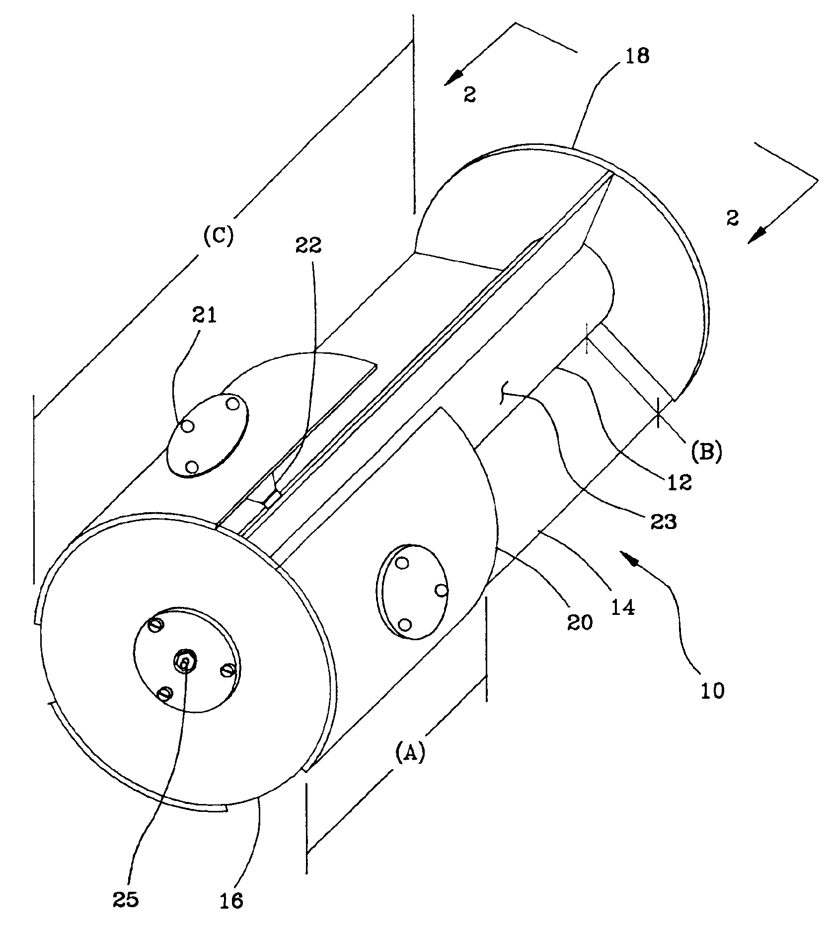
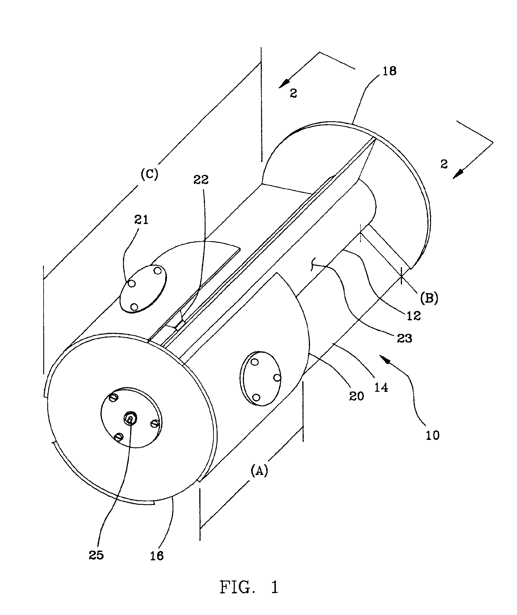
Referring now to the drawings wherein like numerals refer to like elements throughout the several views, one sees that FIG. 1 depicts the gravity-actuated submarine antenna 10 of the present invention. The antenna 10 is preferably cast with a rigid thickness from aluminum with brass electrically conductive components attached. Other commonly acquired materials or methods known to those skilled in the art may be used in forming the antenna 10. Such a variant in antenna formation would be molding the antenna 10 from plastic and plating the antenna with a conductive material. Another non-exclusive variant in antenna formation would be molding the antenna 10 from conductive material.

The simplified structure of the antenna 10 generally comprises a cylindrical feed tube 12 with radially extending fins 14 and disk plates 16, 18 secured to ends of the feed tube 12 and the fins 14. A plurality of curved metal plates 20 spaced apart from the fins 14 and projecting from the end plate 16 partia...


PUM


Abstract

An antenna including a feed tube with radial fins and circular plates at the ends of the tube and fins thereby forming a boundary for a plurality of resonant cavities. Curved plates, connected to the tube by switches of a switching system, partially encompass and subtend to the length of the tube. Interior to the tube, a transmission line from an end plate terminus conducts radio-frequency energy from the terminus to a hub and onto a switch of the switching system in which the switch is mechanically reactive to and actuated by a righting action of the curved plates when the curved plates encounter a sea state. When actuated, energy from the switch distributes to a proximate resonant cavity and curved plate to form a radiation pattern based on the difference in phase of the resonant cavity and curved plate.

Description

BACKGROUND OF THE INVENTION(1) Field of the InventionThe present invention relates to antennas and more particularly to radiators for low profile, towed antennas.(2) Description of the Prior ArtPresent submarine communications with battlegroups or shore sites utilize surface antennas for a variety of requirements including SATCOM, LOS, etc. The use of surface antennas typically interferes with the covert operation of the submarine. For example, data exchange or the receipt of commands is accomplished by using antennas within a mast, which must be extended whenever transmission or reception is required. For communications in coastal or littoral areas, raising a mast renders the submarine vulnerable to visual or radar detection. To mitigate such detection, buoyant cable antennas (BCA) are often used. However, current BCAs cannot be used effectively for transmission, due to their extremely low radiation efficiency.Furthermore, antennas towed on the ocean surface are subjected to dynami...

Claims


Application Information

Patent Timeline
IPC IPC(8): H01Q1/04H01Q1/30H01Q1/27H01Q1/00H01Q1/34
CPCH01Q1/04H01Q1/34H01Q1/30
Inventor RIVERA, DAVID F.
Owner THE UNITED STATES OF AMERICA AS REPRESENTED BY THE SECRETARY OF THE NAVY
Why Eureka
Try Eureka