
Dispersion compensation using resonant cavities

a resonant cavity and dispersion compensation technology, applied in the field of dispersion compensation systems and methods, can solve the problems of limiting the distance that high data rate optical signals can be transmitted through optical fibers, fiber dispersion, and chromatic dispersion becoming critical issues,

Inactive Publication Date: 2005-02-22
OPLINK COMM
View PDF2 Cites 4 Cited by
  • Summary
  • Abstract
  • Description
  • Claims
  • Application Information

AI Technical Summary

Benefits of technology

It is an advantage of embodiments of the present invention to provide a system and method for dispersion compensation using resonant cavities.
It is a further advantage of embodiments of the present invention to provide a system and method for dispersion compensation using resonant cavities wherein the sum of the dispersions in each of a series of GTIs provides greater system bandwidth and selectable local dispersion slopes.
It is a further advantage of embodiments of the present invention to provide a system and method for dispersion compensation using compact resonant cavities with minimal insertion loss.
It is a further advantage of embodiments of the present invention to provide a system and method for tunable dispersion compensation for broadband simultaneous compensation for fibers of various lengths and dispersions.

Problems solved by technology

At these extremely high data rates, the modulation bandwidth is so large that even for an ideal source without chirp or phase noise, fiber dispersion, and particularly chromatic dispersion, becomes a critical issue.
Therefore, fiber dispersion limits the distance that high data rate optical signals can be transmitted through optical fibers.
However, planar waveguides suffer from polarization-mode dependent dispersion and high sensitivity to temperature.
However, the useful depth of compensation in a single GTI is not adequate for long-distance, broadband applications.
Furthermore, narrow bandwidth dispersions create problems in GTI-based resonant dispersion filters.
However, due to the narrow effective wavelength range in their system's channels, this method is rarely used in actual CDC systems, and no further investigation was reported.
However, this device cannot be used to be CDC device because the amplitude of negative dispersion is too small (<10 ps / nm).

Method used


Image

  • Dispersion compensation using resonant cavities
  • Dispersion compensation using resonant cavities
  • Dispersion compensation using resonant cavities

Examples


Embodiment Construction

In the following description of preferred embodiments, reference is made to the accompanying drawings which form a part hereof, and in which is shown by way of illustration specific embodiments in which the invention may be practiced. It is to be understood that other embodiments may be utilized and structural changes may be made without departing from the scope of the preferred embodiments of the present invention.

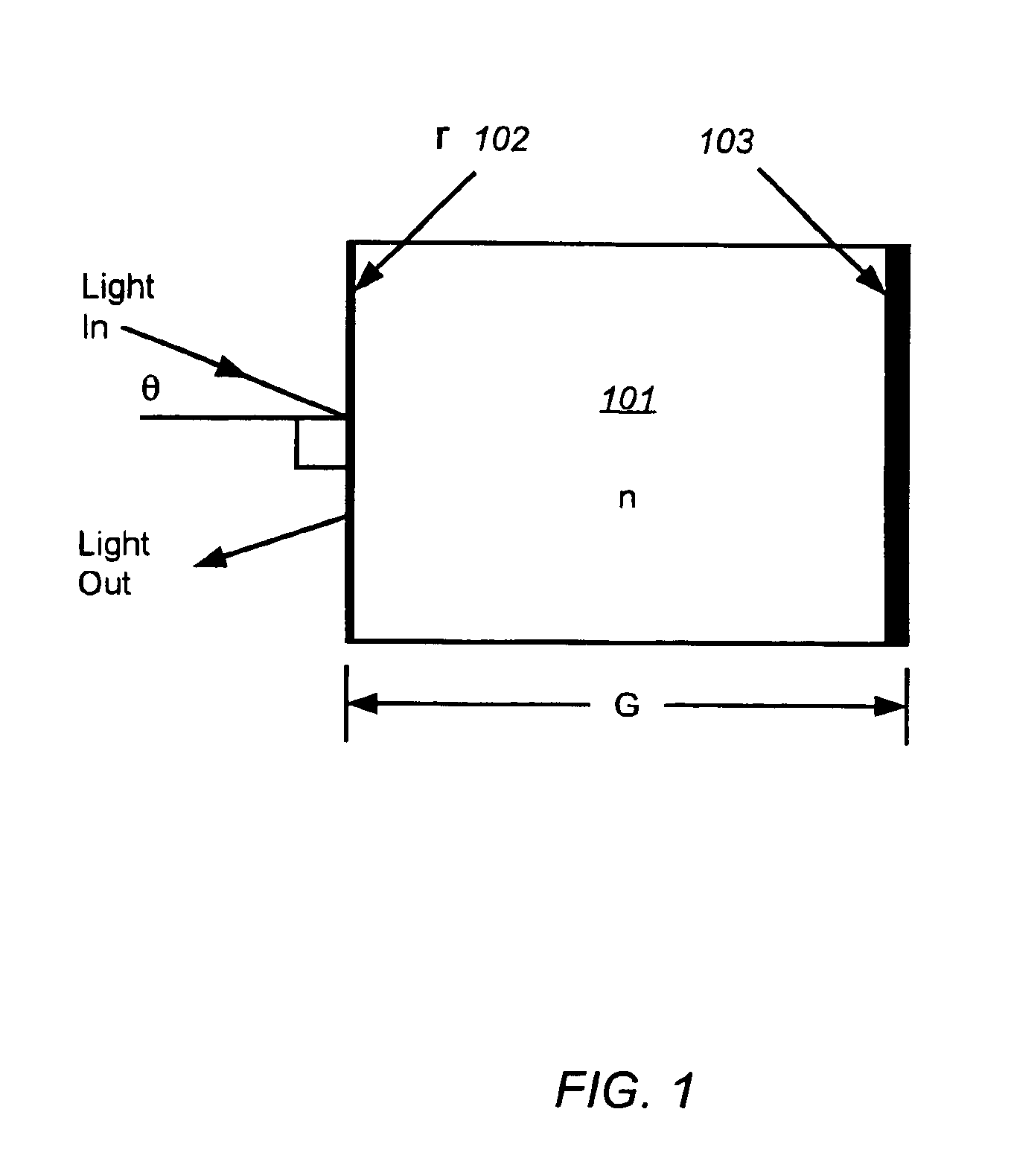
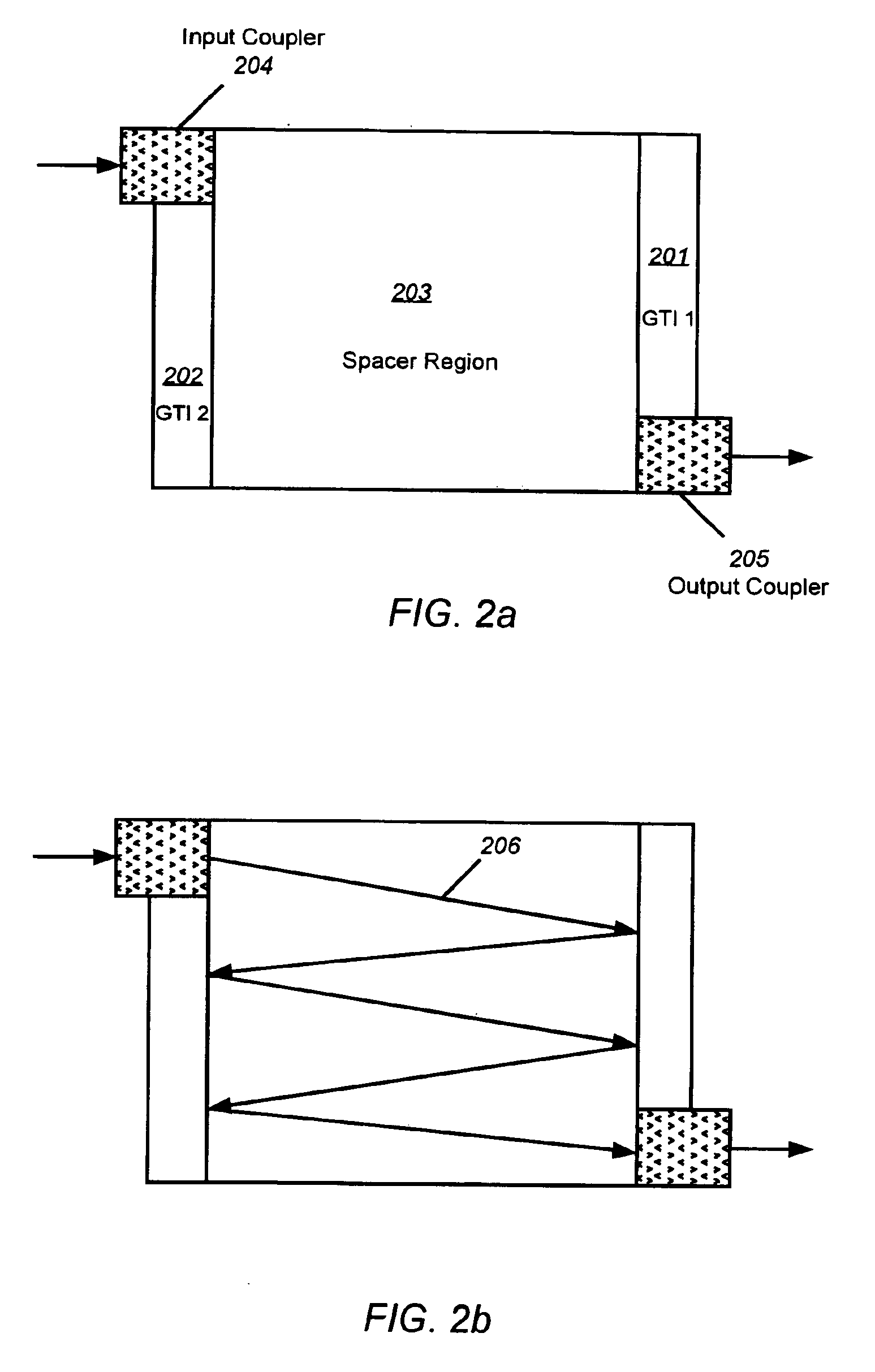
Multi-stage, all-pass optical filters can be used to make low-loss, multi-channel dispersion compensation modules. The all-pass optical filters can be ring resonators in waveguides, GTIs in free space form, and the like. The embodiments of the present invention discussed herein concentrate on free-space GTI-based all-pass dispersion filters for purposes of explanation and illustration, but it should be understood that all forms of GTI-based dispersion filters fall within the scope of the present invention. These dispersion filters include, but are not limited to, a loop o...


PUM


Abstract

Multi-stage, all-pass optical filters used to make low-loss, multi-channel dispersion compensation modules are disclosed. The all-pass optical filters can be ring resonators in waveguides, Gires-Tournois Interferometers (GTIs) in free space form, and the like. The coupling constants and circulating path lengths may also be distinctively varied in each of the series of GTIs, tuning the net dispersion spectrum of the GTI set, such that the sum of the dispersions from the series of GTI's can provide a system with greater bandwidth than the same number of identical GTIs. The local dispersion slope can also be tuned in this manner. Multi-cavity GTIs can also be formed with similar performance enhancing properties.

Description

BACKGROUND OF THE INVENTION1. Field of the InventionThe present invention relates, generally, to dispersion compensation systems and methods and, in preferred embodiments, to dispersion compensation using resonant cavities, and bandwidth and slope improvements in resonant dispersion filters.2. Description of Related ArtOptical fiber systems have the potential for achieving extremely high communication rates, such as in the OC-192 and OC-768 high data rate systems. At these extremely high data rates, the modulation bandwidth is so large that even for an ideal source without chirp or phase noise, fiber dispersion, and particularly chromatic dispersion, becomes a critical issue. Fiber dispersion broadens the optical pulse and causes pulse spreading due to increased spectral width over long propagation distances. Therefore, fiber dispersion limits the distance that high data rate optical signals can be transmitted through optical fibers. The higher the data rate, the shorter the distanc...

Claims


Application Information

Patent Timeline
Patent Type & Authority Patents(United States)
IPC IPC(8): G02B26/00G02B5/28G02B6/34G02B6/32
CPCG02B5/284G02B6/29358G02B6/29394G02B26/001G02B6/29395G02B6/325G02B6/327
Inventor YEH, POCHI ALBERTCAMPBELL, SCOTT PATRICKXU, ZHILING
Owner OPLINK COMM
Learn More