Check patentability & draft patents in minutes with Patsnap Eureka AI!

Monitor apparatus for sequential-function-chart-type programmable controller

a programmable controller and sequential function technology, applied in the direction of electric controllers, program control, electric programme control, etc., can solve the problems of large amount of time and labor, stoppage among a large number of active steps, and the inability to know the branched path and the step or steps through which the control is carried out, so as to achieve the effect of quick determination of a step

Inactive Publication Date: 2005-02-22
TOYODA MASCH WORKS LTD
View PDF18 Cites 17 Cited by
  • Summary
  • Abstract
  • Description
  • Claims
  • Application Information

AI Technical Summary

Benefits of technology

In view of the foregoing, an object of the present invention is to provide a monitor apparatus for an SFC-type PLC which solves the above-described problems and which enables quick determination of a step which is a cause of stoppage of a facility.
Another object of the present invention is to provide a monitor apparatus for an SFC-type PLC which can cope with a program including selective branches and which easily finds a route through which control has reached a presently-active step.
Alternatively or additionally, the monitor apparatus comprises an execution monitor unit for storing data indicating whether each step in the SFC program has been executed; and the display unit displays the program in such a manner that a step or steps which have been executed are distinguished from a step or steps which have not yet been executed, on the basis of the data stored in the execution monitor unit. In this case, an execution history of the program can be found easily.

Problems solved by technology

When a failure occurs in such a facility, each of the programs executed in parallel includes a step which is active at the time of occurrence of the failure, and therefore, a huge amount of time and labor is needed to specify a step which causes the stoppage among a large number of active steps.
However, under a conventional technique, it is impossible to know a branched path and a step or steps through which the control has reached the step which is active at present.

Method used


Image

  • Monitor apparatus for sequential-function-chart-type programmable controller
  • Monitor apparatus for sequential-function-chart-type programmable controller
  • Monitor apparatus for sequential-function-chart-type programmable controller

Examples


Embodiment Construction

An embodiment of the present invention will be described with reference to the drawings.

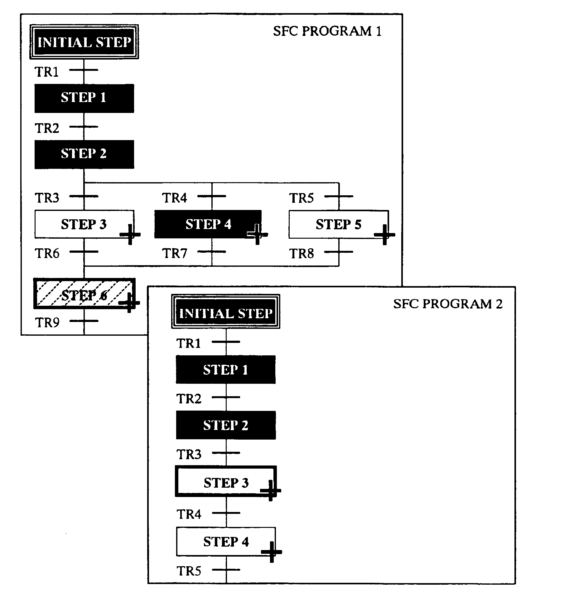
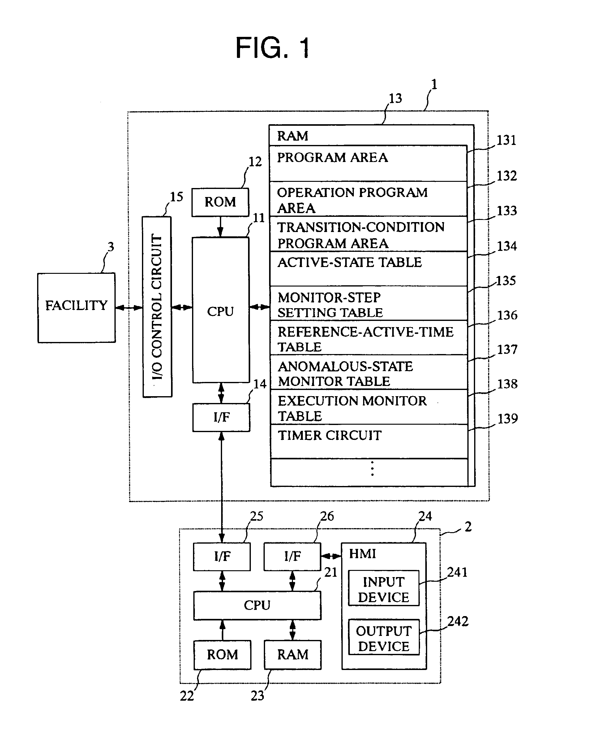
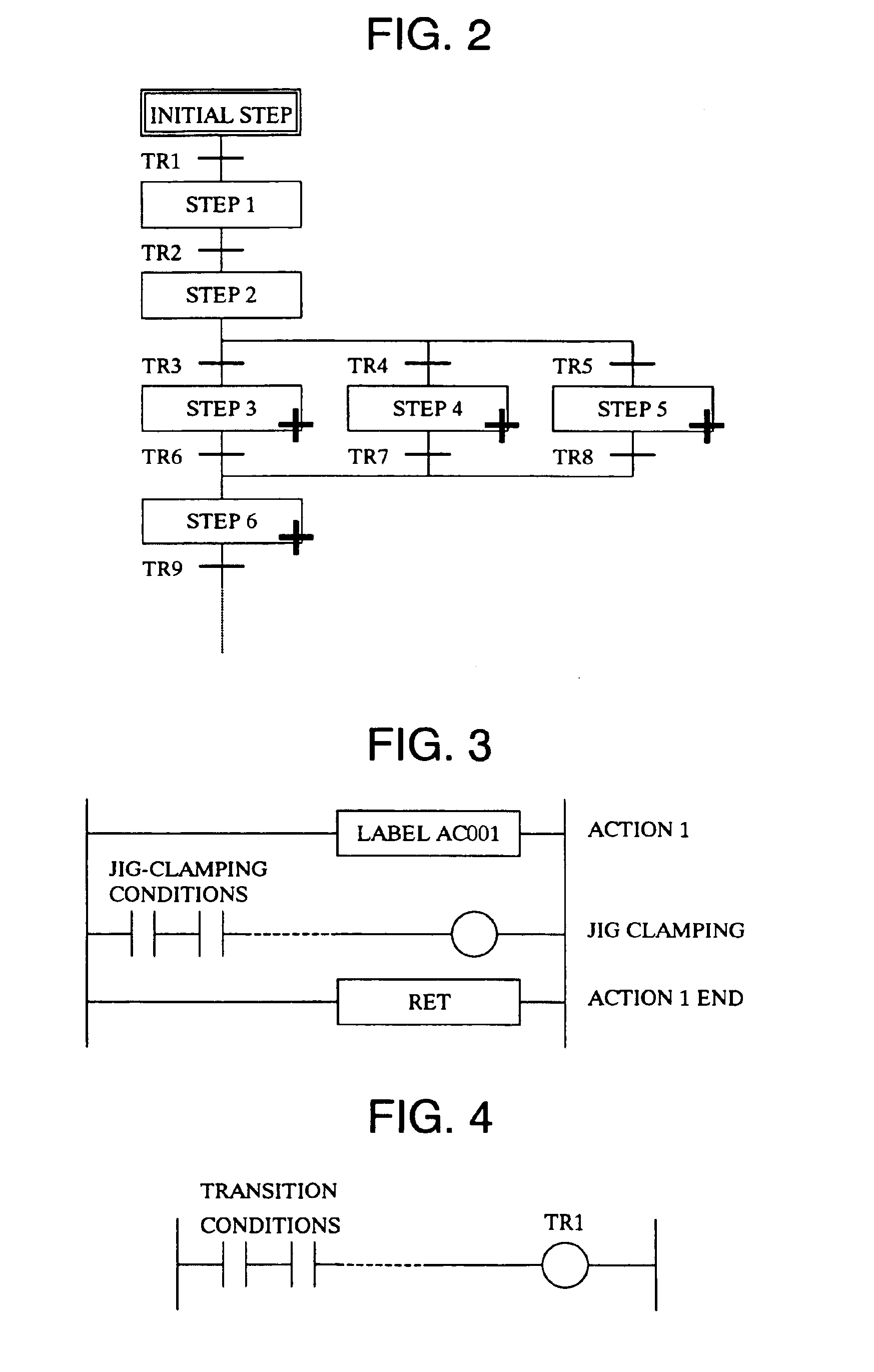
FIG. 1 is a control block diagram showing a PLC 1, a peripheral apparatus 2 connected to the PLC 1, and a facility 3 controlled by the PLC 1.

The PLC 1 includes a CPU 11 serving as a calculation section; ROM 12 storing a system program and other necessary data; RAM 13 having a program area 131 for storing SFC programs, and areas for storing various tables, which will be described later; an interface 14 for exchanging data with the peripheral apparatus 2; and an I / O control circuit 15 for exchanging input and output signals (I / O signals) with the facility 3.

The peripheral apparatus 2 is constituted by a computer, such as a personal computer, and includes a CPU 21 serving as a calculation section; ROM 22 storing a system program and other necessary data; RAM 23 storing various control programs, including a program for display processing, which will be described later; a human-machine-interface (HMI)...


PUM


Abstract

In a monitor apparatus for a sequential-function-chart-type programmable controller, a standard value of an active time of an arbitrary step in a sequential-function-chart program is stored, and the active time of the arbitrary step is measured during execution of the program. An anomalous state of the arbitrary step is detected through comparison between the measured active time and the reference value. Further, data indicating whether each step in the sequential-function-chart program has been executed are stored. The program is displayed such a manner that an anomalous step, a step or steps which have been executed, and a step or steps which have not yet been executed are distinguished from one another.

Description

BACKGROUND OF THE INVENTION1. Field of the InventionThe present invention relates to a monitor apparatus for a programmable controller (hereinafter referred to as a “PLC”), and more particularly to a monitor apparatus which is used with a sequential-function-chart (hereinafter referred to as an “SFC”)-type PLC and which can detect an anomalous state and monitor an operation history.2. Description of the Related ArtSFC is a standard programming language for PLCS and is defined in Draft IEC 1131-1 of IEC (International Electrotechnical Commission). SFC programs have been utilized in place of conventional ladder programs, because of easiness of preparing software in modules and short execution time required for executing the entire program in each scan cycle. The decrease in execution time is achieved through selective execution of activated steps. In an SFC program, steps and transitions are connected as in a flowchart. Each step represents an operation or processing module, whereas e...

Claims


Application Information

Patent Timeline
IPC IPC(8): G05B19/05G05B23/02G06F9/32
CPCG05B19/056G06F9/32
Inventor YAMASHITA, TSUYOSHIFUJISAKI, MASAHARUKATO, HIDETOSHITAKAHARA, HIROYUKI
Owner TOYODA MASCH WORKS LTD
Features
  • R&D
  • Intellectual Property
  • Life Sciences
  • Materials
  • Tech Scout
  • Unparalleled Data Quality
  • Higher Quality Content
  • 60% Fewer Hallucinations
Learn More