Fuel filter including slow release additive

a technology of additives and fuel filters, applied in the field of fuel filters, can solve the problems of reducing reliability, significantly increasing vehicle reducing engine performance and fuel efficiency, etc., and achieves the effect of releasing the fuel additive(s) into the fuel, reducing maintenance and operating costs, and preferably sustained and more preferably controlled

Inactive Publication Date: 2005-03-01
DOBER CHEMICAL CORPORATION +1
View PDF193 Cites 106 Cited by
  • Summary
  • Abstract
  • Description
  • Claims
  • Application Information

AI Technical Summary

Benefits of technology

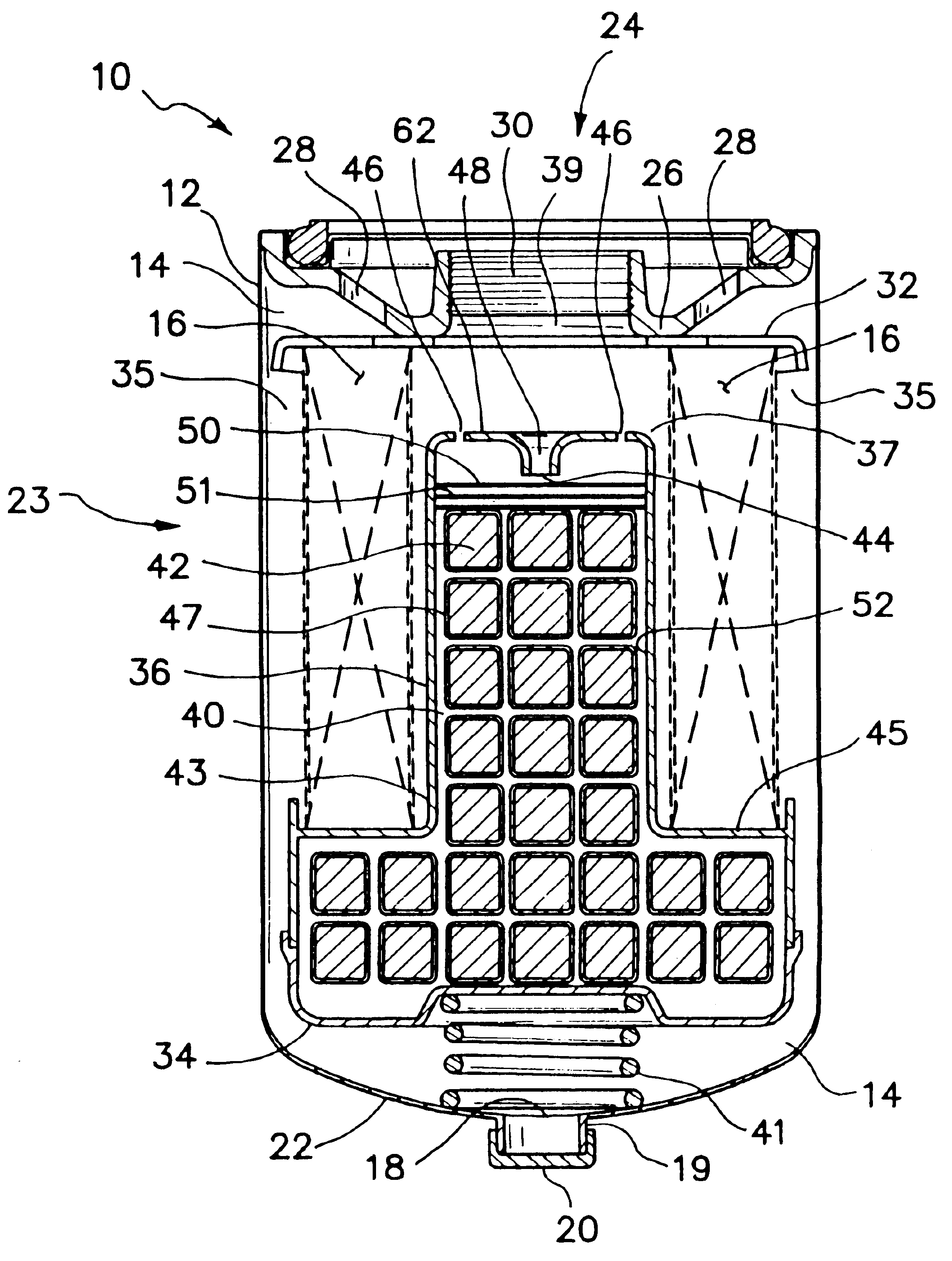
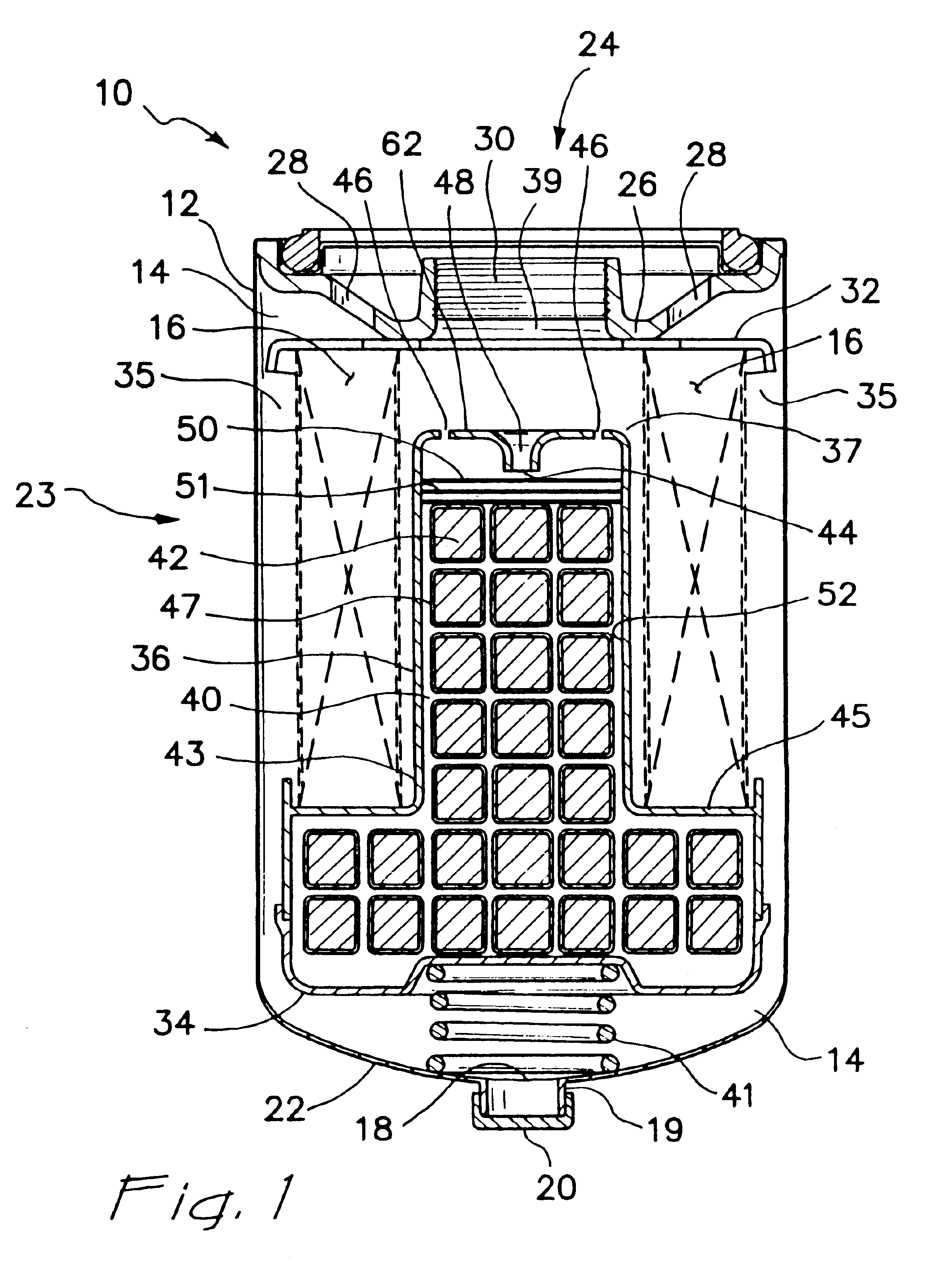
In another form the present invention provides a method of releasing a fuel additive into fuel. The method comprises: providing a fuel filter containing a fuel additive composition, the fuel filter positioned between a source of fuel and an internal combustion engine; contacting a portion of the fuel additive composition with a portion of the fuel to provide a fuel composition comprising fuel and fuel additive; and allowing the fuel composition to admix with the fuel.
In a further form, the present invention provides a method of releasing a fuel additive into fuel. This method comprises providing a fuel additive composition comprising a matrix material and an additive component located, for example, distributed, preferably substantially uniformly distributed, in the matrix material and effective, when released into the fuel, to provide at least one benefit to the fuel. The matrix material comprises at least one polymeric material and is (1) substantially insoluble in the fuel and / or (2) effective to reduce the rate of release of the additive component into the fuel relative to an identical composition without the matrix material. The fuel additive composition is contacted with the fuel, thereby releasing additive component from the fuel additive composition into the fuel.
Another object of the present invention is to provide for effective, preferably sustained and more preferably controlled, release of fuel additive(s) into fuel.

Problems solved by technology

The fuel filter filters out the asphaltenes and bacteria; however, in the process the asphaltenes and bacteria block the fuel filter element.
The blocked filter exhibits a reduced fuel flow and increases the pressure differential across the filter element, thereby reducing engine performance and fuel efficiency.
For many vehicles, particularly commercial trucks that travel thousands of miles a month, this significantly increases vehicle maintenance and operating costs and can reduce reliability.
This is often difficult.
It is difficult to maintain a constant or desired level of an additive in the fuel.
While many bottled fuel additives are commercially available, often operators do not consistently add the additive with each fill-up.
The additive might not be readily available or the operator may forget to include the additive.
When the additive is added to the fuel tank, it does not always form a homogeneous mixture with the fuel.
Fuel tanks do not include reliable methods for mixing fuel.

Method used


Image

  • Fuel filter including slow release additive
  • Fuel filter including slow release additive
  • Fuel filter including slow release additive

Examples


example 1

500 g of Lubrizol OS#69593 dispersant / detergent and 500 g of a commercially available polyethylene wax are provided. The polyethylene wax is heated to a temperature above its melting point, for example, about 140° C. The dispersant / detergent is slowly combined with the molten polyethylene wax with constant stirring until all the dispersant / detergent is included and a substantially uniform mixture is formed. The mixture is then cooled and formed into tablets, using conventional techniques and equipment. The tablets include the dispersant / detergent distributed substantially uniformly in a polyethylene wax matrix.

example 2

600 g (50% by weight Lubrizol OS#69593 in 50% by weight polyethylene (PE wax) in the form of tablets is coated with 191 g of commercially available polyethylene / vinyl acetate copolymer latex over a period of 21 minutes to form coated tablets. Pan speed is 20 rpm, airflow 38 to 52 ft3 / min, air inlet temperature ranges from about 42° C. to about 57° C. (about 45° being preferred) and exhaust temperature ranges from about 27° C. to about 32° C. The tablets tumble well and there is virtually no “twinning.” Tablets with a dry coating weight of 12.7% are obtained. The tablets have a dull finish and uniform orange peel appearance under the microscope. After standing, blocking of the tablets is apparent.

example 3

800 g of the uncoated tablets having a composition as set forth in Example 2 are placed in the coating unit. A total of 365 g of commercially available polyethylene / vinyl acetate copolymer latex is sprayed and about 25 g of coated tablets are removed approximately every 10 minutes to obtain tablets with increasing coating weights. Total run time is 39 minutes. Pan speed is 20 rpm, airflow is 38 to 42 ft3 / min, air inlet temperature ranges from 43° C. to 56° C. and exhaust temperature ranges from 27° C. to 30° C. Tablets with 3.2, 9.7, 15.6 and 18.3% coating (dry weight) are obtained with every 10 minute intervals. The tablets have a dull finish and uniform orange peel appearance under the microscope. After standing, blocking of the tablets is apparent.


PUM

PropertyMeasurementUnit
melting pointaaaaaaaaaa
diameteraaaaaaaaaa

Abstract

This invention relates to a fuel filter for use with internal combustion engines. The fuel filter includes a fuel additive that can be released into fuel. The rate of release for the fuel can be controlled. In one form the fuel additive can be mixed with a matrix material and released at a substantially constant rate to maintain a uniform level of fuel additive in the fuel. Use of the present invention provides a fuel filter having an extended life span that is longer than fuel filters typically used with combustion engines.

Description

BACKGROUND OF THE INVENTIONThe present invention relates generally to a fuel filter for use with internal combustion engines, for example, but not limited to diesel engines in commercial vehicles. More specifically, the present invention is directed to a fuel filter containing a fuel additive that can be released into fuel and a method of releasing the additive into the fuel.Fuel filters are necessary components used to protect combustion engines by filtering out contaminants and thereby preventing damage to the engine and other downstream components such as valves, fuel injectors, fuel lines and related components. Fuel can entrain a wide variety of contaminants from a number of sources. Frequently fuel oxidizes and forms resinous materials such as varnishes commonly referred to as asphaltenes. Bacteria can grow in fuel, particularly fuel that contains moisture. The growing bacteria forms a “slime” on inner surfaces of fuel tanks, fuel lines and fuel filters. The slime often slough...

Claims


Application Information

Patent Timeline
Patent Type & Authority Patents(United States)
IPC IPC(8): B01D37/00B01D37/02B01D27/00C10L1/10F02M25/00F02M37/22F02M37/00F02M37/32F02M37/54
CPCB01D27/00B01D37/025F02M25/00F02M37/22C10L1/10Y10T428/2998F02M37/54F02M37/32
Inventor MARTIN, HAROLDSTEHOUWER, DAVID M.DROZD, JOSEPH C.CHEN, YU-SEN
Owner DOBER CHEMICAL CORPORATION
Why Eureka
Try Eureka