Methods and apparatus for unloading a screw compressor

a screw compressor and compressor technology, applied in the direction of machines/engines, liquid fuel engines, positive displacement liquid engines, etc., can solve the problems of uneconomical and impractical switching the compressor on and off, unloading the compressor, and adding considerable equipment costs, etc., to facilitate the start-up of the motor

Inactive Publication Date: 2005-03-01
DRILTECH MISSION
View PDF5 Cites 26 Cited by
  • Summary
  • Abstract
  • Description
  • Claims
  • Application Information

AI Technical Summary

Benefits of technology

The method and apparatus can be used to unload a screw compressor to facilitate the start-up of a motor that drives the screw compressor, or economize the operation of the motor as it drives the screw compressor during periods when the need for compressed air is low.

Problems solved by technology

For example, a clutch could be provided between the engine and the screw compressor to unload the compressor during periods of low air requirements, but that would add considerable cost to the equipment, and the clutch would rapidly wear in situations where the compressor has to be unloaded frequently.
It is uneconomical and impractical to switch the compressor on and off at frequent intervals.
Another possible energy-saving measure involves the provision of a variable speed gear drive for unloading the screw compressor, but such a drive is complicated and relatively expensive, as would be a two-speed gear drive with clutches.
However, such drives are relatively inefficient (80% maximum), so any energy savings realized during periods of low compressed air consumption would be lost during periods of high air compressed consumption.

Method used


Image

  • Methods and apparatus for unloading a screw compressor
  • Methods and apparatus for unloading a screw compressor
  • Methods and apparatus for unloading a screw compressor

Examples


Embodiment Construction

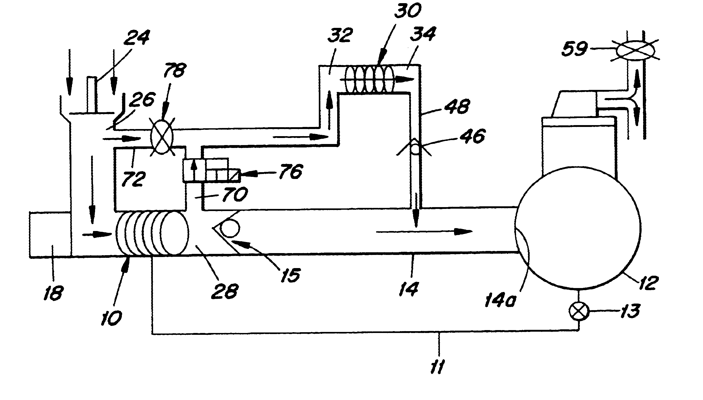
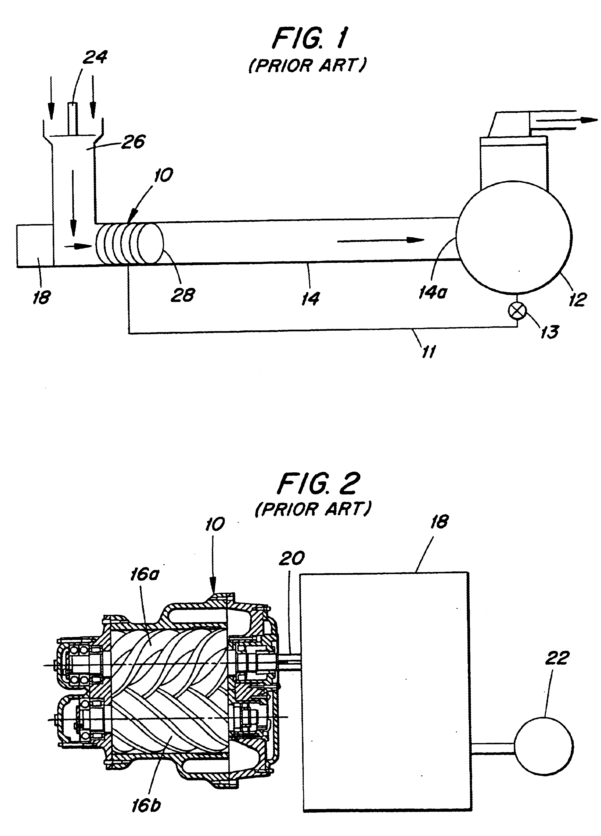
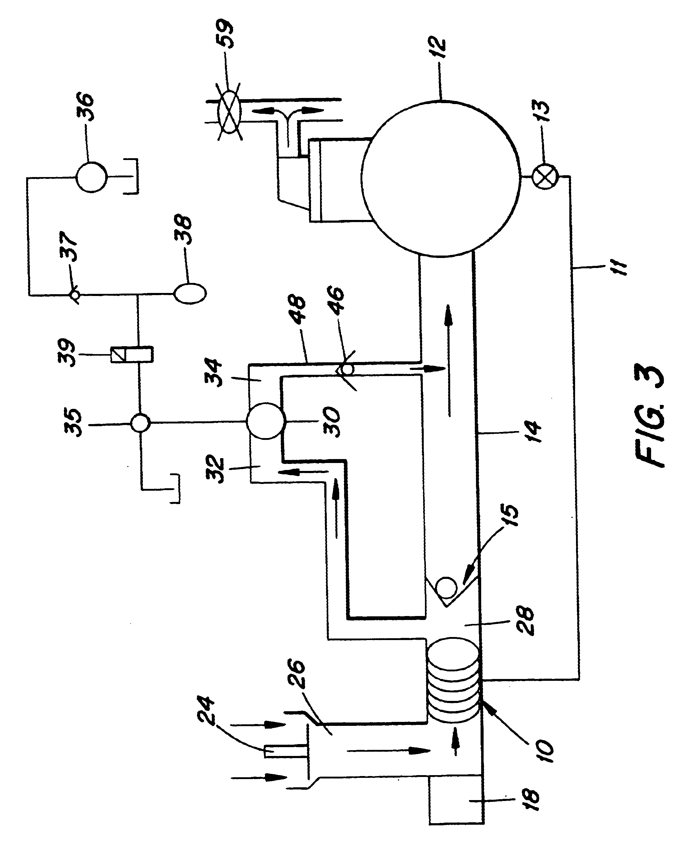
Depicted in FIG. 1 is a conventional air compressing system in which air is compressed by a screw compressor 10, the compressed air being conducted through a main air discharge passage 14 having a discharge outlet 14a connected to an inlet of the air reservoir 12. The air reservoir 12 stores compressed air and contains lubricating oil that is supplied to the main screw compressor 10 by way of a conduit 11 to lubricate, seal and cool the main screw compressor. The oil is injected into the main screw compressor due to a pressure difference between the air reservoir and the main screw compressor. Alternatively a pump (not shown) could be provided for injecting the oil into the main screw compressor. A valve 13 is provided for closing the conduit 11 when the motor 18 and the main screw compressor 10 have been shut down.

The main screw compressor 10 preferably employs a pair of intermeshing screws 16a, 16b as shown in FIG. 2. The screws are driven by a motor 18 through a suitable drive co...


PUM


Abstract

A screw compressor is connected to a motor to be driven by the motor even during periods of low compressed air consumption. During such periods, the screw compressor is at least partially unloaded to make it easier and less costly to drive the compressor. The unloading is performed by removing air from the compressor. Preferably, that is done by communicating the air inlet of a small capacity vacuum device with the air outlet of the screw compressor. Suction from the vacuum device is transmitted to the air outlet of the screw compressor to suck air out of the screw compressor to reduce the engine horsepower needed to rotate the screw compressor. The vacuum device can also be used to boost the air volume and / or the air pressure. The system can be used in a drilling rig which drills holes in the ground. The screw compressor can be unloaded during start up of the motor by briefly driving the vacuum device by pressurized liquid from a pre-pressurized hydraulic accumulator.

Description

BACKGROUND OF THE INVENTIONThe present invention relates to air compression systems, in particular to such systems employing a screw compressor driven by a motor such as a diesel engine or an electric motor, which also drives other equipment, and which continues to drive such equipment as well as the screw compressor even during periods of low compressed air consumption.Motor-driven screw compressors provide a source of compressed air that performs many useful functions. Screw compressor systems have gained acceptance and significant growth due to their robustness, compactness and reliability. Designed for long periods (normally over 100,000 hours) of continuous operation, they provide up to 98% online availability. Their low maintenance costs together with their high energy efficiency minimizes operating costs. The smooth running action of the rotors enables screw compressors to handle the most difficult gases, contaminants, or liquid slugs without vibration.Among the many examples...

Claims


Application Information

Patent Timeline
Patent Type & Authority Patents(United States)
IPC IPC(8): F04B23/12F04B23/00F04B23/08F04C18/16F04C28/06
CPCF04B23/08F04C28/06F04B23/12F04C18/16
Inventor LEPPANEN, JARMO
Owner DRILTECH MISSION
Why Eureka
Try Eureka