Eureka AIR delivers breakthrough ideas for toughest innovation challenges, trusted by R&D personnel around the world.

Recovery and re-use of anode oxygen from electrolytic cells

Inactive Publication Date: 2005-03-01
HATCH LTD
View PDF8 Cites 17 Cited by
  • Summary
  • Abstract
  • Description
  • Claims
  • Application Information

AI Technical Summary

Benefits of technology

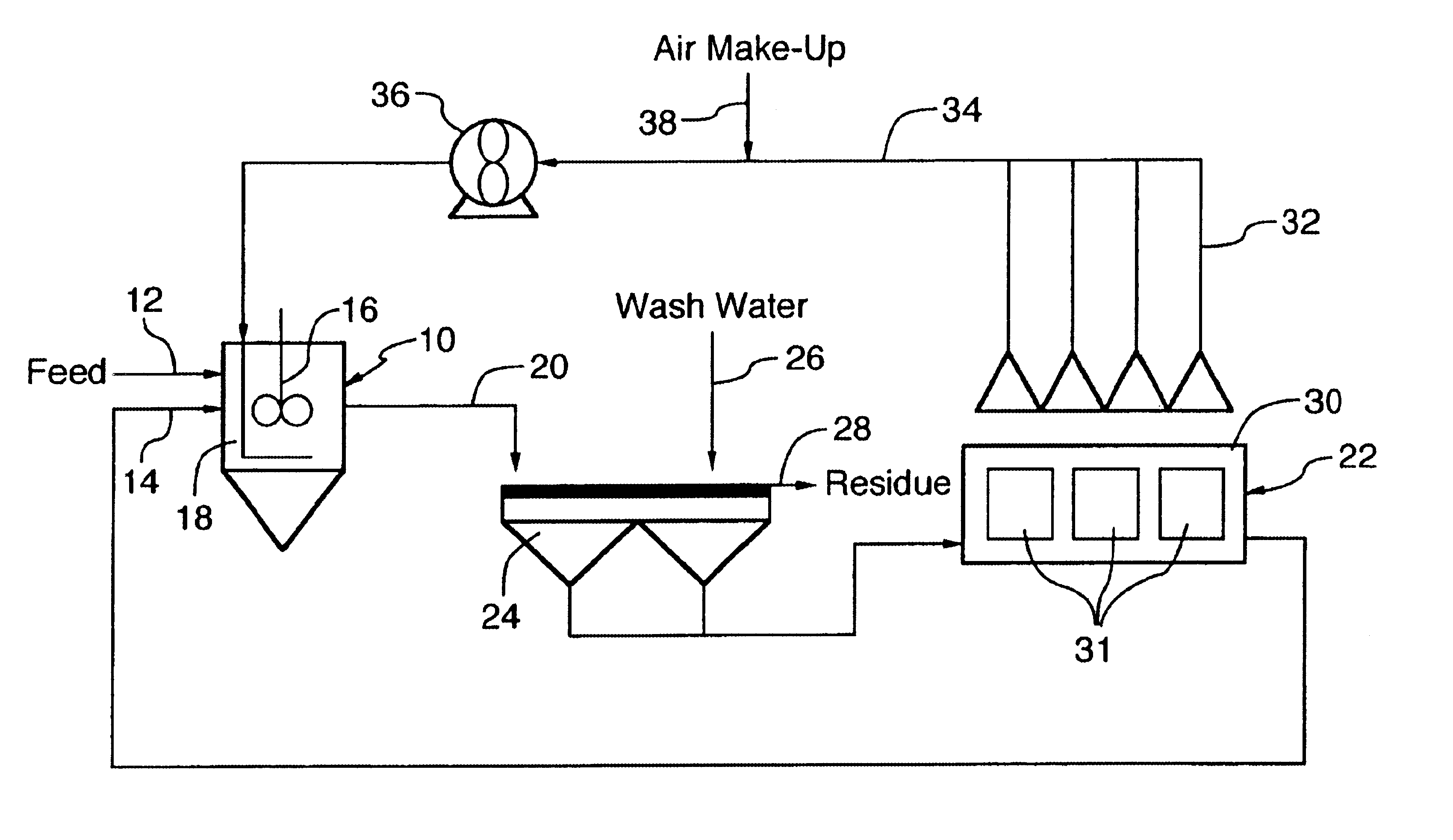
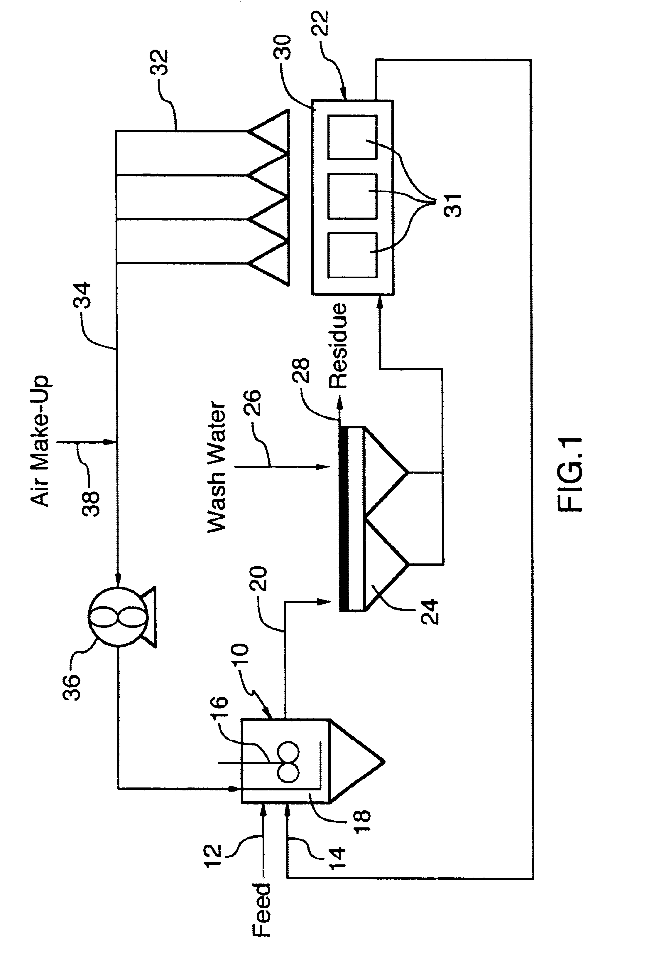
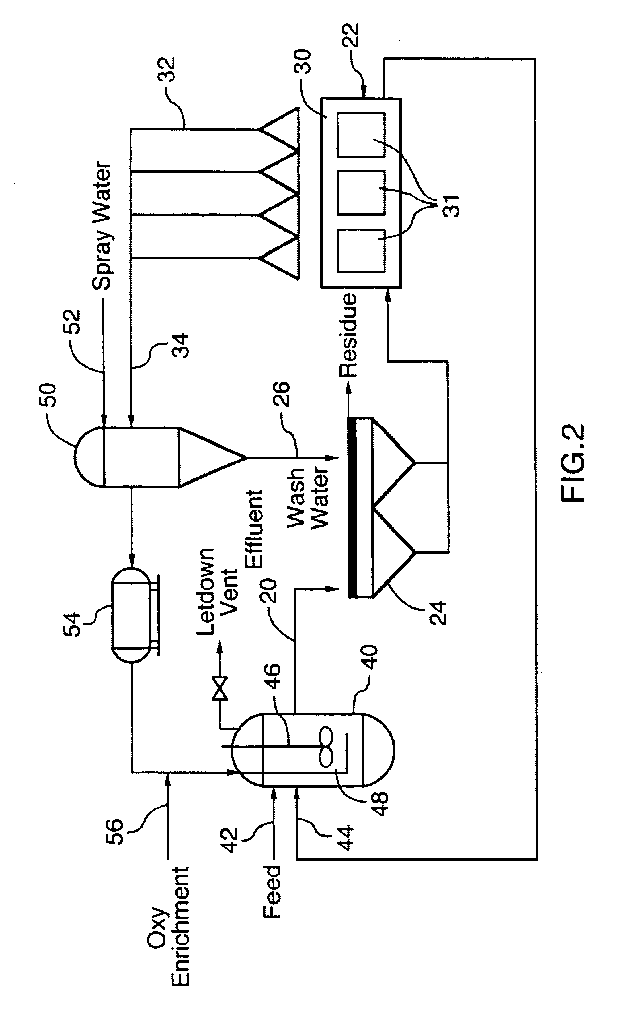
Preferably, the anode oxygen is recovered and re-used in an atmospheric or pressure leaching step. The leaching step comprises treatment of a feedstock as defined above with a leaching solution, usually an acidic aqueous solution. Leaching can be conducted either at atmospheric pressure (“atmospheric leach”) or at elevated pressures (“pressure leach”) in an autoclave. During the leaching process, metal compounds contained in the feedstock are converted to metal salts and are dissolved in the aqueous solution. Oxygen is usually added to the aqueous solution during the leaching process in order to maximize metal recovery and to minimize corrosion of plant equipment. The leachate produced during the leaching process is subsequently subjected to electrowinning to recover the metals from solution.
The recovery and re-use of anode oxygen is expected to provide additional cost savings, improved metal recoveries, improved throughput or improved impurity, the benefits being partly dependent on the oxygen-consuming step to which the anode oxygen is recirculated. Therefore, the present invention is expected to make mist-reducing technology more attractive in existing installations and in new installations.

Problems solved by technology

This acidic mist is corrosive and hazardous to health of workers in the electrowinning tankhouse.
The consumption of electrons by hydrogen ions can significantly reduce current efficiency in the electrolytic cell.
However, the application of mist-reducing technology to older facilities can be challenging and expensive, and the benefits are usually insufficient to justify the capital commitment needed to modify existing infrastructures to accommodate the technology.

Method used


Image

  • Recovery and re-use of anode oxygen from electrolytic cells
  • Recovery and re-use of anode oxygen from electrolytic cells
  • Recovery and re-use of anode oxygen from electrolytic cells

Examples


examples

To ascertain the feasibility of limiting air dilution of the anode oxygen gases to 5% by volume, a typical example of an individual electrowinning cell is discussed below. Although electrowinning cells vary in shape and design, rough dimensions can be used to estimate the significance of 5% air dilution. In this example, the following type of cell is utilized:Commodity plated: nickelCathode wetted width: 1 meterCathode wetted height: 1 meterCathode current density: 250 Amps / m2 Current efficiency: 90% (bagged anodes)

In this type of cell, each cathode is fed 500 Amps, of which 450 Amps (90%) is utilized to plate nickel, with the rate of nickel plating being approximately 0.49 kg / hour. The rate of anode oxygen generation would be slightly less than 0.13 kg / hour. Assuming a gas temperature of 60° C. and gas pressure of 100 kPa, this would equate to a volumetric oxygen production per anode of approximately 0.11 m3 per hour.

In this type of cell, the rate of oxygen production at each anode...


PUM

PropertyMeasurementUnit
Percent by massaaaaaaaaaa
Percent by volumeaaaaaaaaaa
Temperatureaaaaaaaaaa

Abstract

A process and apparatus for recovering a metal from a feedstock containing a compound of the metal. The process includes an electrowinning step in which a leachate comprising a salt of the metal, dissolved in an aqueous acid solution, is subjected to electrowinning in an electrolytic cell, wherein elemental metal is deposited on the cathodes of the cell and oxygen is generated at the anodes. The oxygen generated at the anodes is collected and is then at least partially consumed in an oxygen-consuming step of the process. Preferably, the oxygen-consuming step comprises an atmospheric or pressure leaching step in which the metal compounds in the feedstock become dissolved in a leachate in the form of metal salts, preferably sulfates. The recovery and use of anode oxygen in a leaching process encourages the use of mist-reducing technology in existing and new electrowinning facilities.

Description

FIELD OF THE INVENTIONThis invention relates to the recovery of metals from metal-containing feedstocks by a process including an electrowinning step and an oxygen-consuming step, and particularly to such processes in which oxygen from the electrowinning step is recovered for use in the oxygen-consuming step.BACKGROUND OF THE INVENTIONSome metals can be recovered from feedstocks such as ores, concentrates, mattes or alloys by processes which include an electrowinning step. Examples of such processes include the recovery of cobalt and nickel from feedstocks containing sulfides or oxides of these metals.Electrowinning involves subjecting an electrolyte containing dissolved metal salts to electrolysis. Electrowinning is conducted in one or more electrolytic cells, each cell having a plurality of anode and cathode plates in alternating arrangement. During the electrowinning step, elemental metal is plated out at the cathode and, where the metal salt is a sulfate, for example, oxygen is ...

Claims


Application Information

Patent Timeline
IPC IPC(8): C25C7/06C25C7/00C25C1/08C25C1/00
CPCC22B23/043C25C7/06C25C1/08C25C1/00Y02P10/20
Inventor BELLINO, MARKHARRIS, GARFIELD BRYN
Owner HATCH LTD
Why Eureka
Eureka Blog
Learn More