Hermetically sealed optical subassembly

a technology of optical sub-assembly and hermetically sealed array, which is applied in the direction of optical elements, instruments, photoelectric discharge tubes, etc., can solve the problems of difficult work, tight space within the ceramic substrate within which to mount and wire bond the photodiode array, etc., and achieve the effect of maintaining and optimizing coupling efficiency, increasing the distance from the fiber-ends

Inactive Publication Date: 2005-03-01
OPTICAL COMM PRODS
View PDF7 Cites 66 Cited by
  • Summary
  • Abstract
  • Description
  • Claims
  • Application Information

AI Technical Summary

Benefits of technology

An exemplary embodiment of the present invention provides an optical subassembly including a hermetic seal for protecting optoelectronic devices such as photodetectors and associated components from moisture via a window, transparent to light from the fiber. In another embodiment, the window is decoupled from direct contact with certain components of the optical subassembly, such as the metal FSA retainer, that have coefficients of thermal expansion which differ significantly from that of the window. In another embodiment, the window also enables an increase in the distance from the fiber-ends to the face of the optoelectronic device while maintaining and optimizing coupling efficiency.

Problems solved by technology

As it is typically necessary to place the photodiode array a relatively short distance from the ends of the fibers to maintain sufficient optical coupling, the space within the ceramic substrate within which to mount and wirebond the photodiode array is often tight and difficult to work with.

Method used


Image

  • Hermetically sealed optical subassembly
  • Hermetically sealed optical subassembly
  • Hermetically sealed optical subassembly

Examples


Embodiment Construction

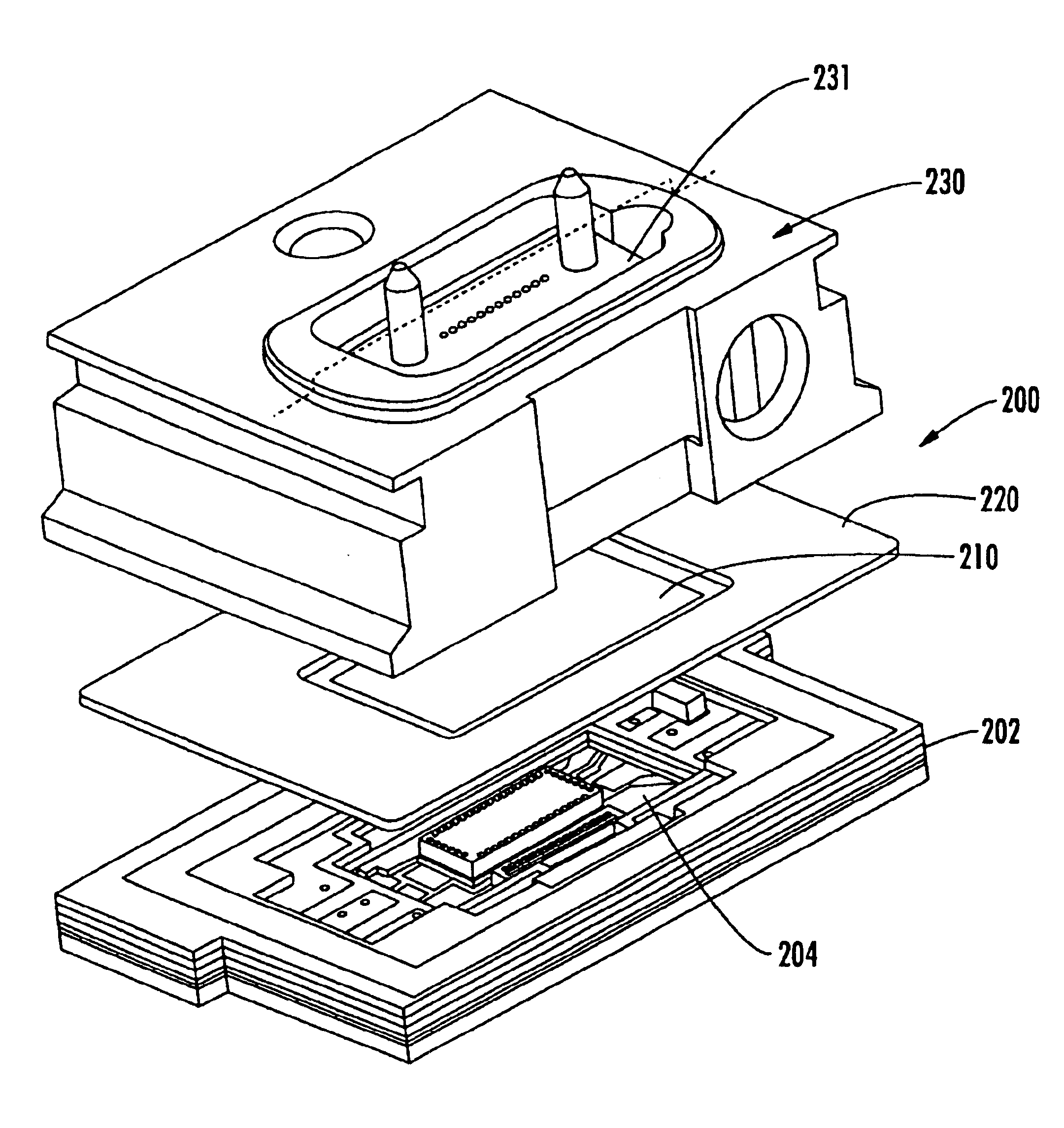
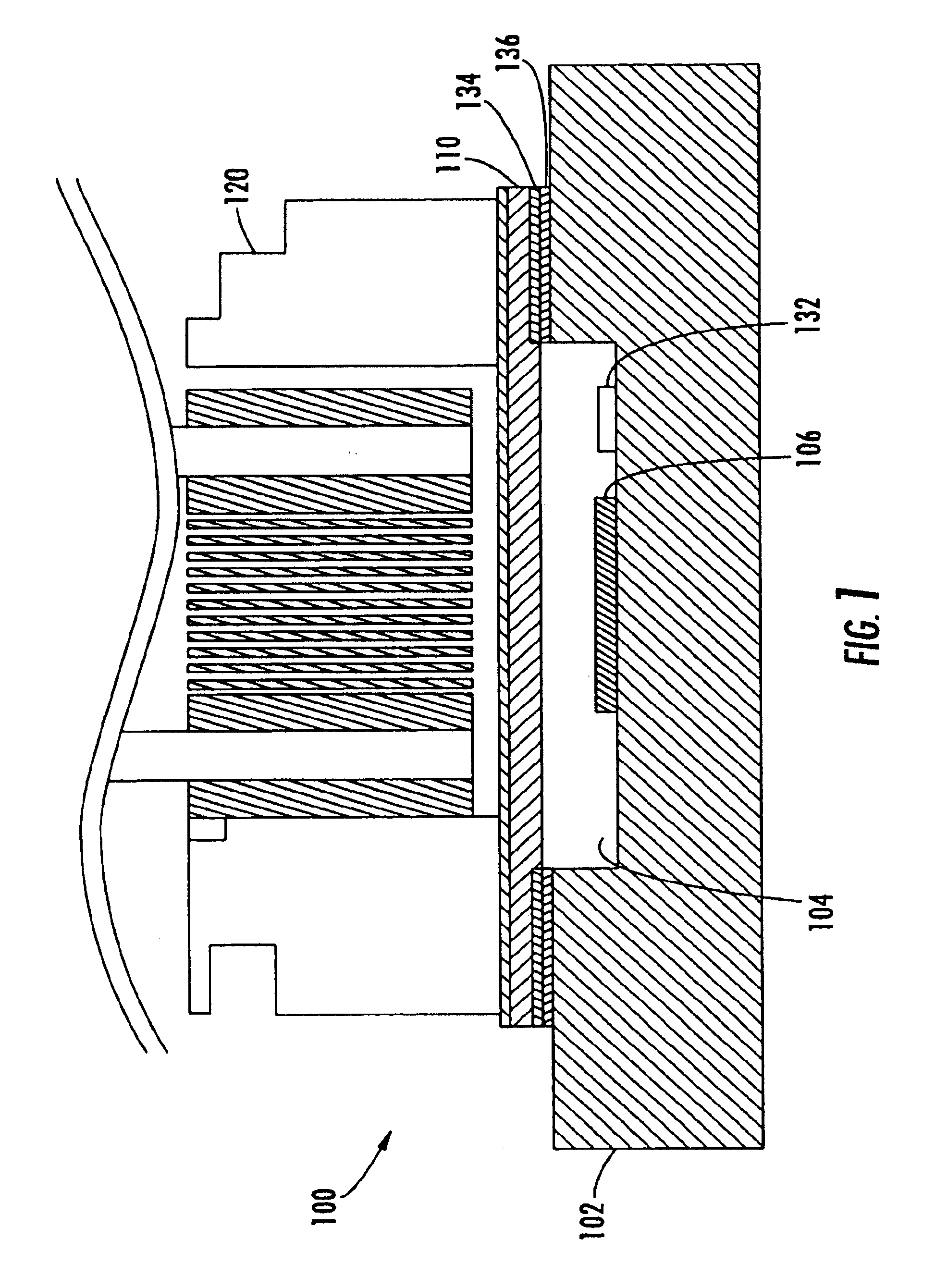
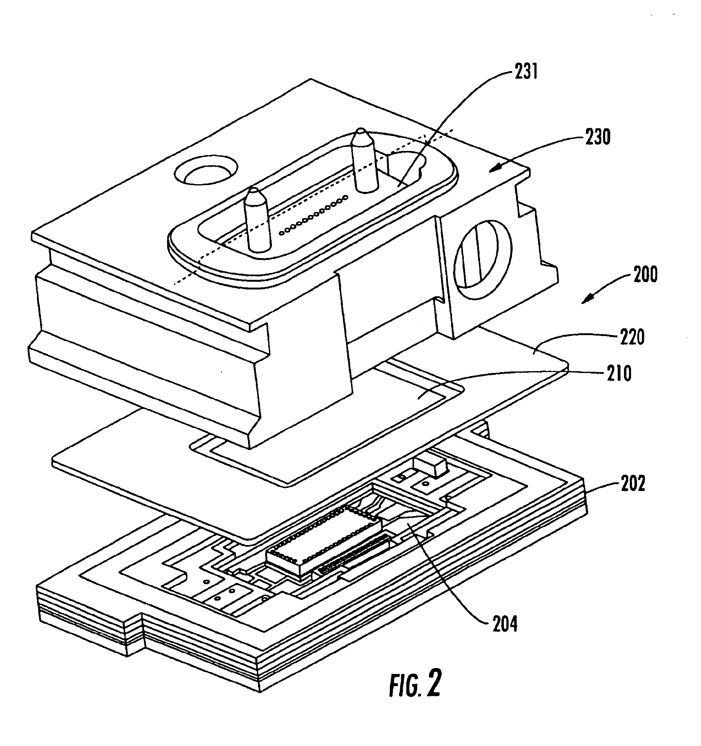
Referring to FIG. 1, a ROSA 100 according to one embodiment includes a ceramic substrate 102 with a cavity 104, an optoelectronic device such as a photodetector array die (e.g., PIN array) 106, a window 110 and a fiber stub array (FSA) retainer 120. The window 110 may be silicon, glass, sapphire or other material that passes some or all of the light at the wavelength of the optoelectronic device. The retainer 120 typically couples the ROSA to a conventional MT type ferrule connector (not shown) or similar connector. Alternatively, as is known in the art, a bridging device (231) may be used to provide an interface to the ferrule. For convenience, the MT ferrule or any coupling or bridging device formed as part of the optical subassembly is referred to herein as the FSA retainer. Further, the terms “FSA retainer” or “retainer” as used herein are meant to include any mechanism for facilitating attachment of one or more optical fibers to the assembly. The cavity 104 houses the PIN array...


PUM


Abstract

An optical subassembly includes a high speed ceramic substrate having cavity containing an array of photodetectors, and a glass or silicon window for covering the cavity and forming a hermetic seal. A retainer is attached to the window for direct or indirect attachment to a fiber. The hermetic seal protects the device from moisture and other environmental conditions. The window has an index of refraction higher than air that effectively increases the optical pathlength sufficient while maintaining an acceptable coupling efficiency between the optoelectronic device and a fiber. This provides increased spacing within which to place and interconnect components within the cavity on the substrate. In alternate embodiments, the window is decoupled from direct contact with the retainer via a metal frame or ring. Decoupling the window from direct contact with the retainer helps prevent cracking of the window due to mismatches in the coefficients of thermal expansion between the window and the retainer.

Description

FIELD OF THE INVENTIONThe present invention relates generally to optoelectronic receivers, and more particularly to a hermetically sealed array receiver optical assembly (ROSA). Although described herein with respect to ROSAs, it should be understood that the present invention may also be applied to transmitters.BACKGROUNDOptoelectronic devices used in fiber optic communication transmitters and / or receivers are typically required to perform in varying environmental conditions and within tight specifications and tolerances. As the accumulation of moisture may have a detrimental effect on such components, it is beneficial to provide protection of the components from moisture.In the specific case of a photodiode array ROSA on a ceramic substrate, the ROSA typically includes a metal retainer that is directly attached to a ferrule that houses an array of fibers. As it is typically necessary to place the photodiode array a relatively short distance from the ends of the fibers to maintain ...

Claims


Application Information

Patent Timeline
Patent Type & Authority Patents(United States)
IPC IPC(8): G02B6/42
CPCG02B6/421G02B6/4292G02B6/4249G02B6/4248G02B6/4251G02B6/4267
Inventor ADAMS, RICH
Owner OPTICAL COMM PRODS
Why Eureka
Try Eureka