Superconductive magnet device

a superconductive magnet and magnetic field technology, applied in the direction of magnetic bodies, instruments, using reradiation, etc., can solve the problems of affecting the mounting of several tens of ppm in overall error magnetic field components, achieving the desired uniformity, and achieving inferior uniformity. , to achieve the effect of reducing the consumption of expensive liquid helium, and improving the uniformity of the magnetic field

Inactive Publication Date: 2005-03-01
MITSUBISHI ELECTRIC CORP
View PDF12 Cites 25 Cited by
  • Summary
  • Abstract
  • Description
  • Claims
  • Application Information

AI Technical Summary

Benefits of technology

Accordingly, the first supporting member through which the cryogenic containers are supported by the vacuum adiabatic containers can be thinner, and therefore consumption of expensive liquid helium can be reduced.
A further superconductive magnet device according to the invention includes: a pair of oppositely disposed superconductive magnet bodies in which annular superconductive are accommodated; gradient magnetic field coils disposed between the pair of superconductive magnet bodies; a plurality of fine chip-shaped ferromagnetic shims disposed on a surface of the superconductive magnet bodies, so as to improve uniformity of magnetic

Problems solved by technology

In the case of a superconductive magnet device for MRI, in general, a deviation of 1 mm in dimensions or positioning will result in an influence mounting to several tens ppm in overall error magnetic field components.
Particularly in the design of a vertically split type superconductive magnet device, the uniformity tends to be inferior, as compare with the conventional cylindrical solenoid type superconductive magnet device, to such an extent that a positioning error between upper and lower superconductive magnet bodies 14, 15 is added.
Usually, it is difficult to attain a desired uniformity in just one execution of works, and therefore the process has to be repeated several times thus gradually improving the uniformity.
T

Method used


Image

  • Superconductive magnet device
  • Superconductive magnet device
  • Superconductive magnet device

Examples


embodiment 1

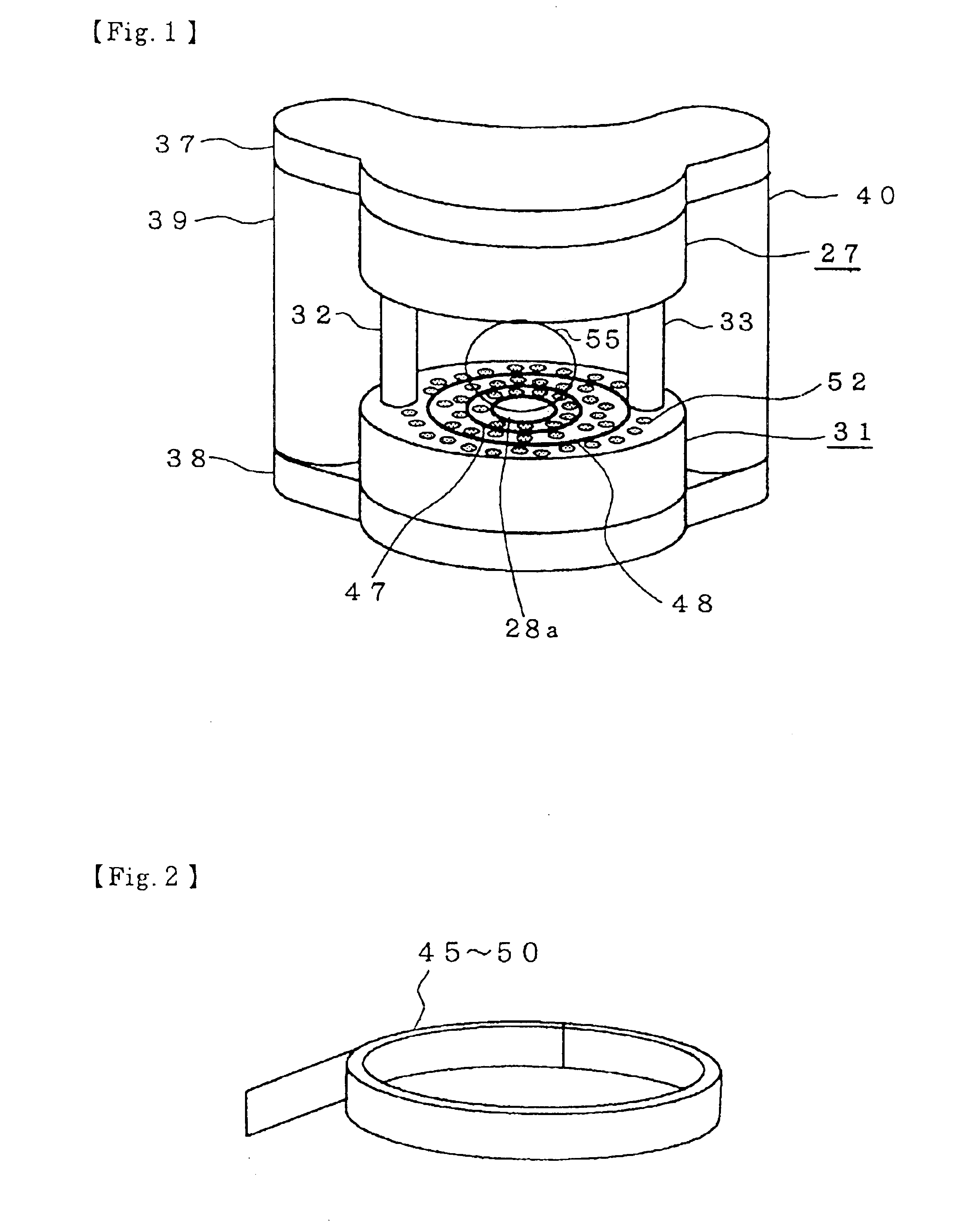
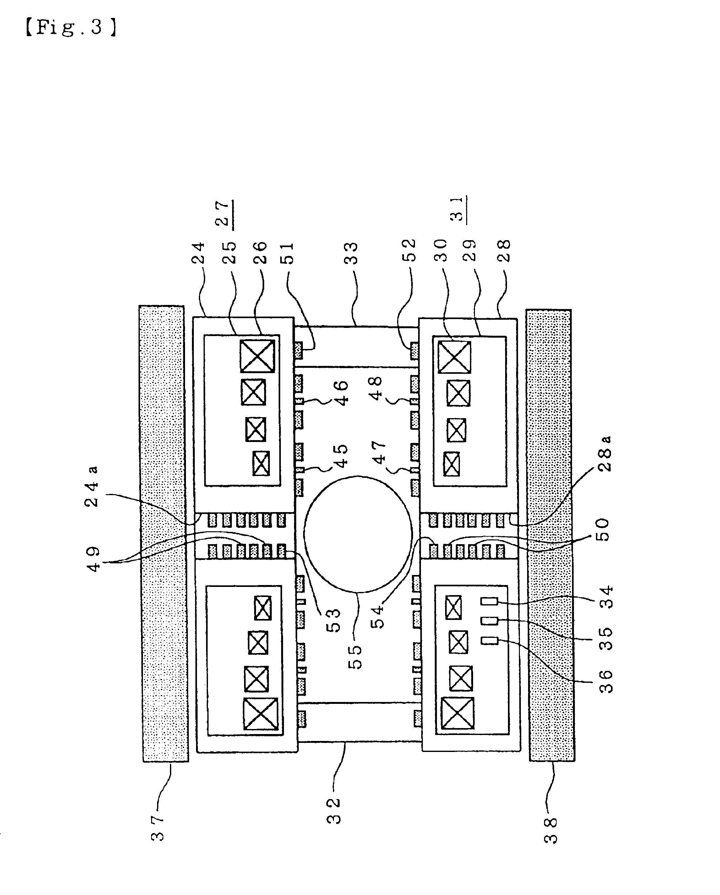
FIG. 1 is a perspective view showing a construction according to Embodiment 1, FIG. 2 is a perspective view showing an essential part of FIG. 1, FIG. 3 is a schematic sectional view of FIG. 1, and FIG. 4 is a sectional view showing an essential part of FIG. 1. Referring to FIGS. 1 to 4, reference numeral 24 is a vacuum adiabatic container placed on the upper side, and in the center of which a bore portion 24a is provided. Numeral 25 is a cryogenic container accommodated inside vacuum adiabatic container 24 and in which liquid helium is sealed. Numeral 26 is an annular superconductive coil accommodated in the cryogenic container 25. The mentioned components 24 to 26 as a whole form a superconductive magnet body 27. Numeral 28 is a vacuum adiabatic container disposed oppositely on the lower part with a predetermined clearance from the vacuum adiabatic container 24, and is provided with a bore portion 28a at the center portion. Numeral 29 is a cryogenic container accommodated inside va...

embodiment 2

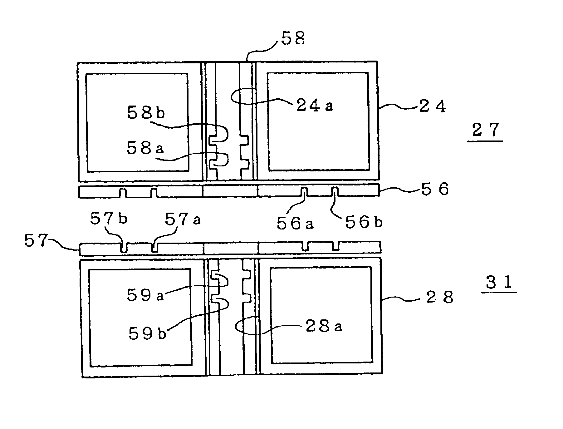
FIG. 5 is sectional view showing a construction of Embodiment 2. Referring to FIG. 5, the superconductive magnet bodies 27, 31 are designated to like parts as in the foregoing Embodiment 1. However, the ring-shaped ferromagnetic shims 45 to 50 are not disposed on either of the superconductive magnet bodies 27, 31. Numeral 56 is a disc-shaped holding member fixed to the superconductive magnet body 27 at its surface opposing to the superconductive magnet body 31, and on which grooves 56a, 56b are formed concentrically with the annular superconductive coil 26 shown in FIG. 3. Numeral 57 is a disc shape holding member fixed to the superconductive magnet body 31 at its surface opposing to the superconductive magnet body 27, and on which grooves 57a, 57b are formed in concentrically with the annular superconductive coil 30 shown in FIG. 3. Numeral 58 is a cylindrical holding member fixed into the bore portion 24a of the superconductive magnet body 27, and on which grooves 58a, 58b are for...

embodiment 3

FIG. 6 is an explanatory diagram showing a distribution of Z even number components generated by ring-shaped ferromagnetic shims according to Embodiment 3.

When designing a group of annular superconductive coils, it is understood that generating some amount of certain Z even number components is more effective for reducing number of annular superconductive coils and total magnetomotive force, rather than adjusting all the error magnetic field components to substantially zero by the annular superconductive coils group alone. In the practical designing, there are various solutions depending on conditions such as restriction in number of annular superconductive coils, manufacturing method thereof, area available for placement, restriction on electromagnetic force, restriction on maximum magnetic field intensity, etc.

FIG. 6 shows variation between outputs of (0, 2) to (0, 8) components and the ring-shaped ferromagnetic shims of different radius when the ring-shaped ferromagnetic shims of...


PUM


Abstract

A superconductive magnet device comprises a pair of oppositely disposed superconductive bodies in which annular superconductive coils are accommodated, and fine chip-shaped ferromagnetic shims disposed on a surface of the pair of superconductive magnet bodies so as to improve uniformity of magnetic field in a uniform magnetic field in a uniform magnetic field space generated in the proximity of the center between the superconductive magnet bodies, wherein ring-shaped ferromagnetic shims are disposed concentrically with the center of annular superconductive coils on the surface of the superconductive magnet bodies.

Description

BACKGROUND OF THE INVENTION1. Field of the InventionThe present invention relates to a superconductive magnet device to improve uniformity of a uniform magnetic field space between a pair of superconductive magnet bodies.2. Background ArtRecently superconductive magnet devices have come to be widely used as a generating source of a static magnetic field that has a high intensity and a temporal stability. In particular, superconductive magnet devices have been popularly employed as a generating source of a static magnetic field in medical tomography equipment (magnetic resonance imaging equipment) or silicon single crystal pickup devices. Most of those conventional superconductive magnet devices were of cylindrical solenoid type, while more popularly used recently are such devices provided with two superconductive magnets horizontally or vertically opposed each other with a large clearance therebetween in order to utilize their large opening and spacious magnetic field area.In the fi...

Claims


Application Information

Patent Timeline
IPC IPC(8): G01R33/3873G01R33/38G01R33/3815
CPCG01R33/3873G01R33/3815
Inventor YOSHIDA, NAOJITANABE, HAJIMEKURODA, SHIGENORI
Owner MITSUBISHI ELECTRIC CORP
Why Eureka
Try Eureka