Multi-site cardiac stimulation device and method for detecting retrograde conduction

Inactive Publication Date: 2005-03-01
PACESETTER INC
View PDF16 Cites 25 Cited by
  • Summary
  • Abstract
  • Description
  • Claims
  • Application Information

AI Technical Summary

Benefits of technology

Retrograde conduction from two or more sites is further confirmed by a mathematical relationship examining the change in atrial rate relative to the change in VP intervals. If retrograde conduction is confirmed for two or more pathways, automatic adjustment of operating parameters, preferably an extension of the post-ventricular atrial blanking period, is made to terminate the pacemaker-mediated tachycardia. Adjustments are also made to prevent inappropriate arrhythmia detection due to the pacemaker-mediated tachycardia.
The stimulation device measures the time delay between the pacing of a ventricular site to the sensed P-wave in the corresponding atrium. The standard deviations of these retrograde conduction times for each ventricular sites are used to derive VP interval stability for different retrograde paths. The study of the relationship between average retrograde conduction stability and atrial heart rate within

Problems solved by technology

Unfortunately, a pacemaker operating in the DDD mode may contribute, in combination with other factors, to a pacemaker-mediated tachycardia (PMT).
Unfortunately, the pacemaker sensing circuits cannot differentiate between retrograde P-waves and normal P-waves, so such sensing may result in a pacemaker-mediated tachycardia wherein each ventricular paced event is followed by a retrograde P-wave which is tracked, resulting in another ventricular paced event, causing the process to repeat.
Such lengthening of the PVARP, however, disadvantageously prevents the sensing of a P-wave that occurs late in the PVARP.
A failure to sense a P-wave, in turn, causes an atrial stimulus to be generated by the pacemaker that is more than likely delivered into the heart's atrial refractory period, at a time when such pulse is ineffective.
This results in an effect

Method used


Image

  • Multi-site cardiac stimulation device and method for detecting retrograde conduction
  • Multi-site cardiac stimulation device and method for detecting retrograde conduction
  • Multi-site cardiac stimulation device and method for detecting retrograde conduction

Examples


Embodiment Construction

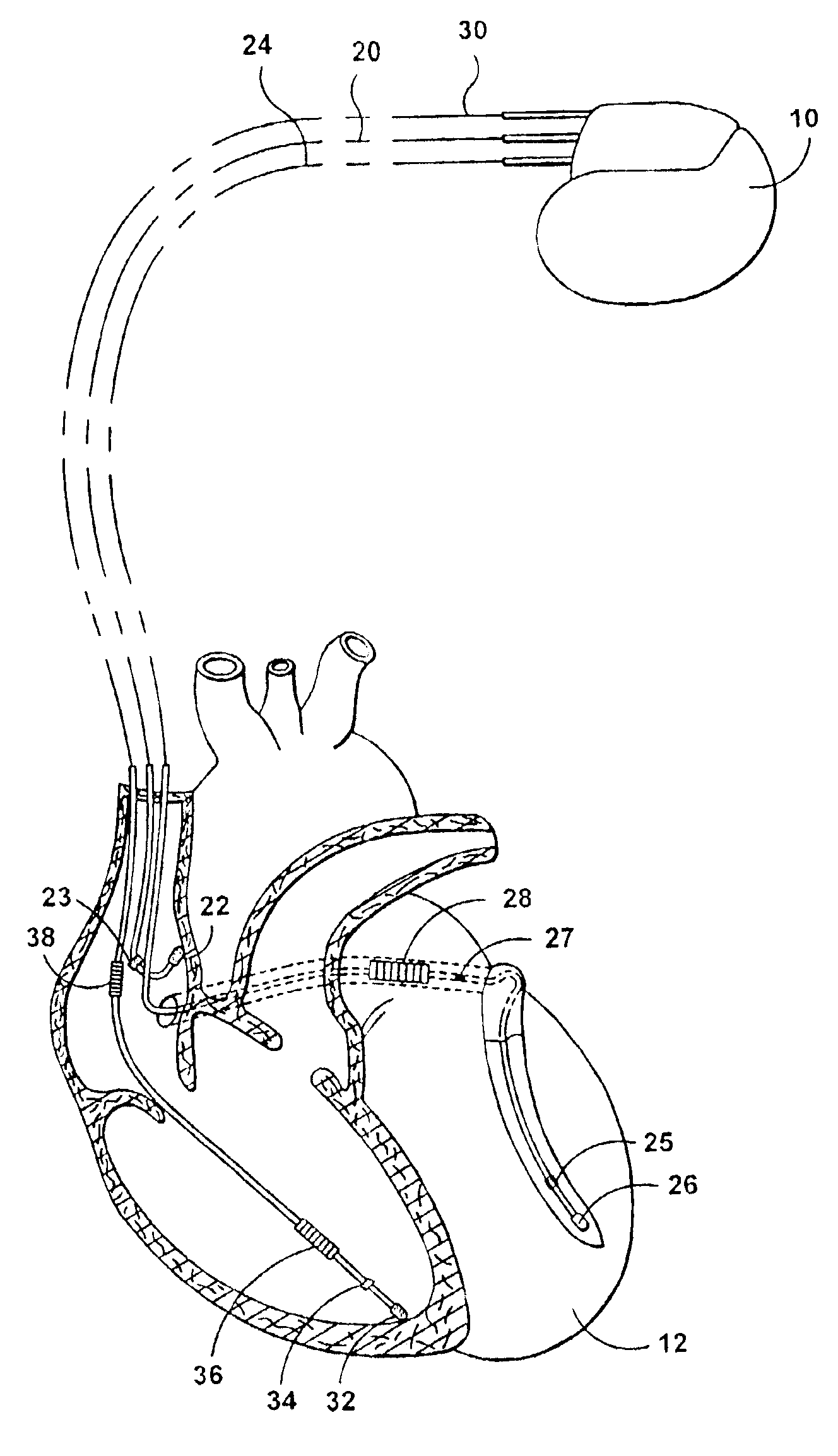
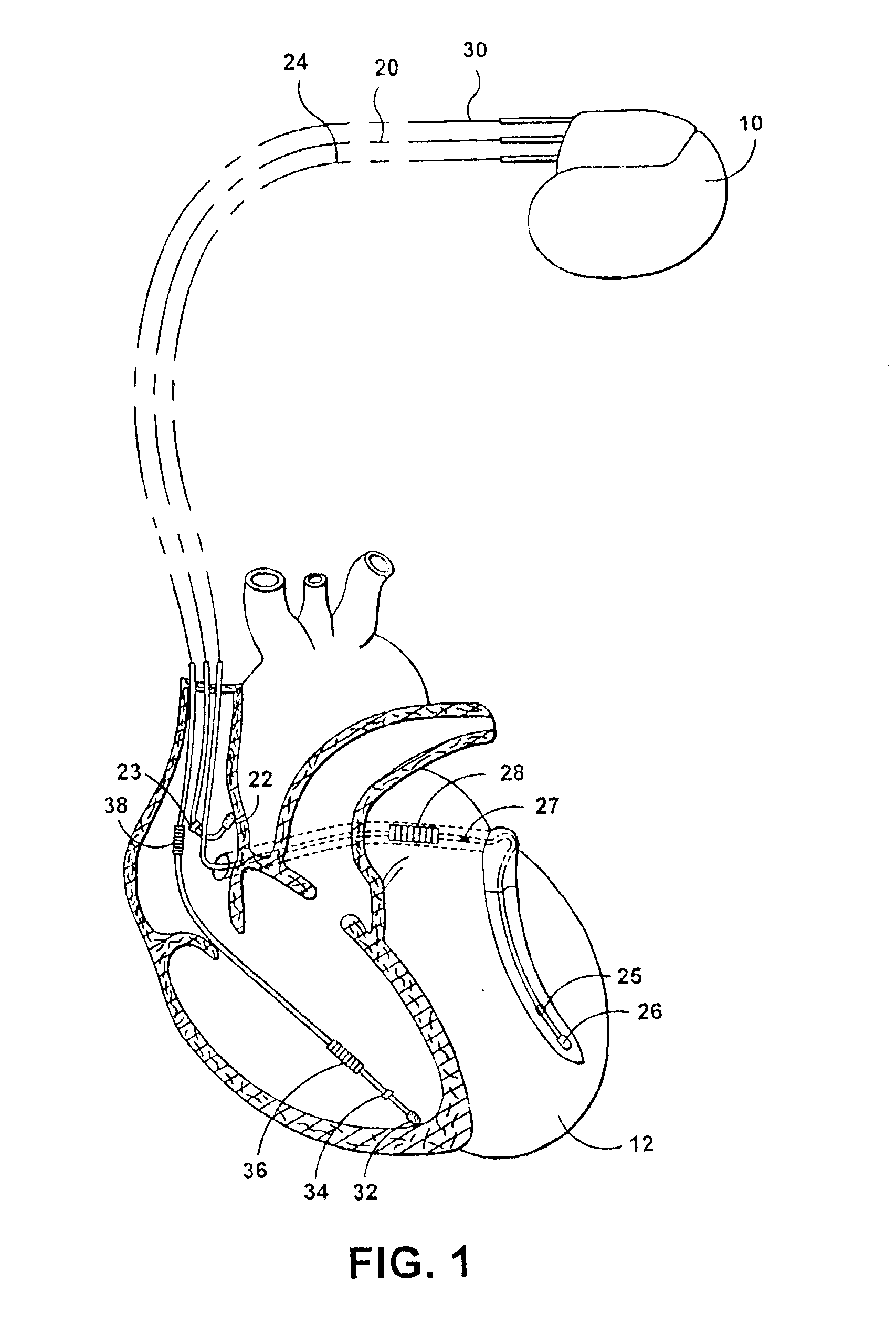
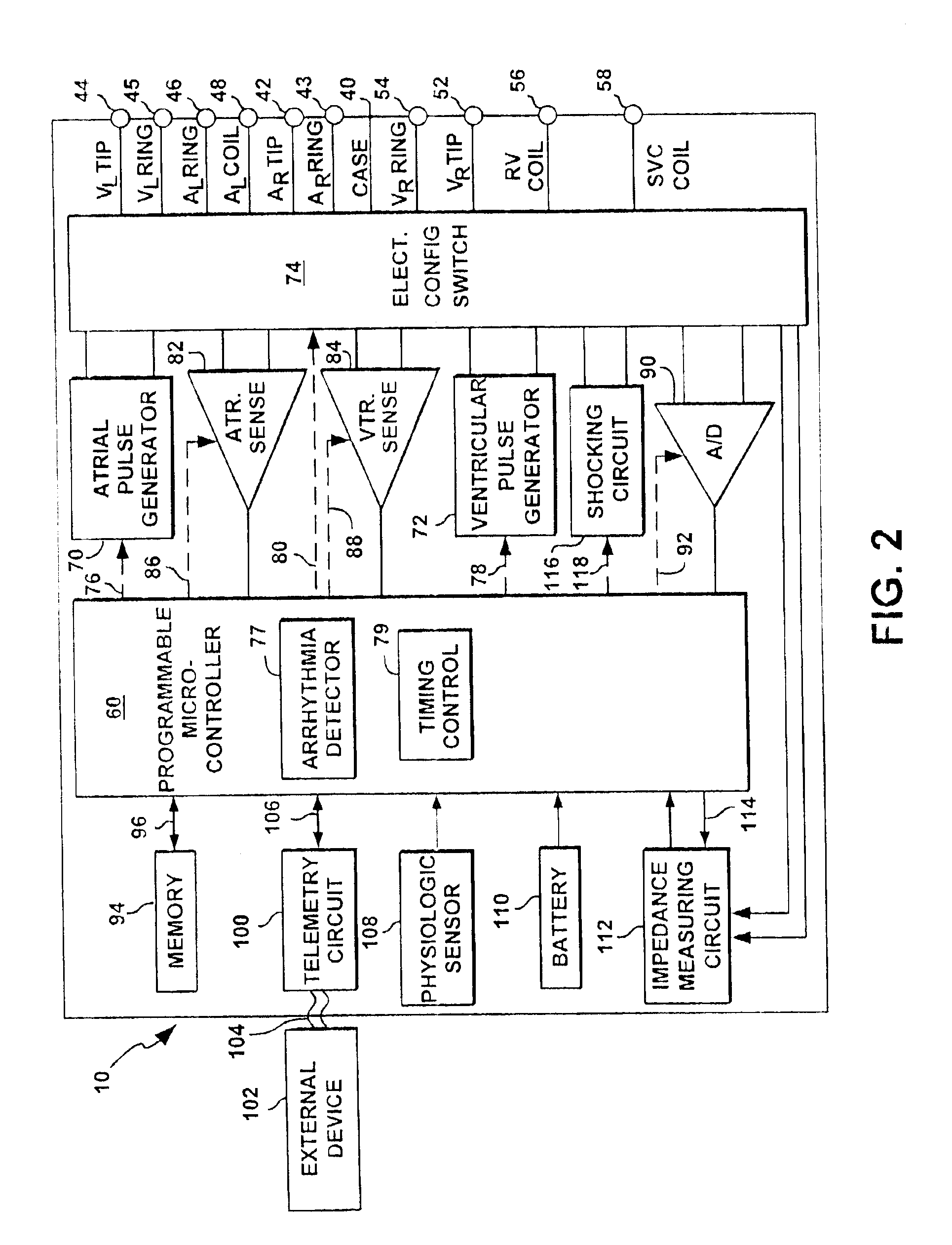
The following description is of a best mode presently contemplated for practicing the invention. This description is not to be taken in a limiting sense but is made merely for the purpose of describing the general principles of the invention. The scope of the invention should be ascertained with reference to the issued claims. In the description of the invention that follows, like numerals or reference designators will be used to refer to like parts or elements throughout. The present invention is directed at detecting retrograde conduction in an implantable cardiac stimulating device possessing pacing, cardioversion and defibrillation capabilities. A general cardiac stimulation device will thus be described in conjunction with FIGS. 1 and 2, in which the retrograde conduction detection feature of the present invention could be implemented. It is recognized, however, that numerous variations of such a device exist in which the methods of the present invention could be implemented wi...


PUM


Abstract

An implantable cardiac stimulation device, such as a pacemaker, defibrillator and/or cardioverter, and an associated method that provide cardiac stimulation to at least two ventricular stimulation sites, within a single ventricle or across two ventricles. A high intrinsic atrial rate triggers a retrograde conduction detection routine when a high ventricular stimulation rate is sustained for a predetermined number of cycles during an atrial sensing mode. This routine interrupts concurrent stimulation, and alternates the stimulation output to the different ventricular sites.

Description

FIELD OF THE INVENTIONThe present invention relates generally to programmable cardiac stimulating devices. More specifically, this is directed to a multi-chamber or biventricular cardiac stimulation device and associated method for detecting retrograde conduction from one or more ventricular stimulation site for the purpose of identifying and terminating pacemaker-mediated tachycardia (PMT).BACKGROUND OF THE INVENTIONIn a normal human heart, the sinus node, generally located near the junction of the superior vena cava and the right atrium, constitutes the primary natural pacemaker initiating rhythmic electrical excitation of the heart chambers. The cardiac impulse arising from the sinus node is transmitted to the two atrial chambers, causing a depolarization known as a P-wave and the resulting atrial chamber contractions. The excitation pulse is further transmitted to and through the ventricles via the atrioventricular (A-V) node and a ventricular conduction system causing a depolar...

Claims


Application Information

Patent Timeline
IPC IPC(8): A61N1/362A61N1/368
CPCA61N1/3622A61N1/3684A61N1/36842A61N1/36843
Inventor MO, ANTHONY
Owner PACESETTER INC
Why Eureka
Try Eureka