Deep ultraviolet unit-magnification projection optical system and projection exposure apparatus

a technology of magnification projection and optical system, applied in the field of deep ultraviolet unit-magnification projection optical system, can solve the problems of reducing the field size of available field to about 25% to 35%, unnecessary pressure compensation, and reducing the field siz

Inactive Publication Date: 2005-03-08
VEECO INSTR
View PDF14 Cites 62 Cited by
  • Summary
  • Abstract
  • Description
  • Claims
  • Application Information

AI Technical Summary

Problems solved by technology

Thus, the resultant system is essentially independent of the index of refraction of the air in the lens, making pressure compensation unnecessary.
The cost of this gain in working space is the reduction of available field size to about 25% to 35% of the total potential field.
However, today

Method used


Image

  • Deep ultraviolet unit-magnification projection optical system and projection exposure apparatus
  • Deep ultraviolet unit-magnification projection optical system and projection exposure apparatus
  • Deep ultraviolet unit-magnification projection optical system and projection exposure apparatus

Examples


example designs

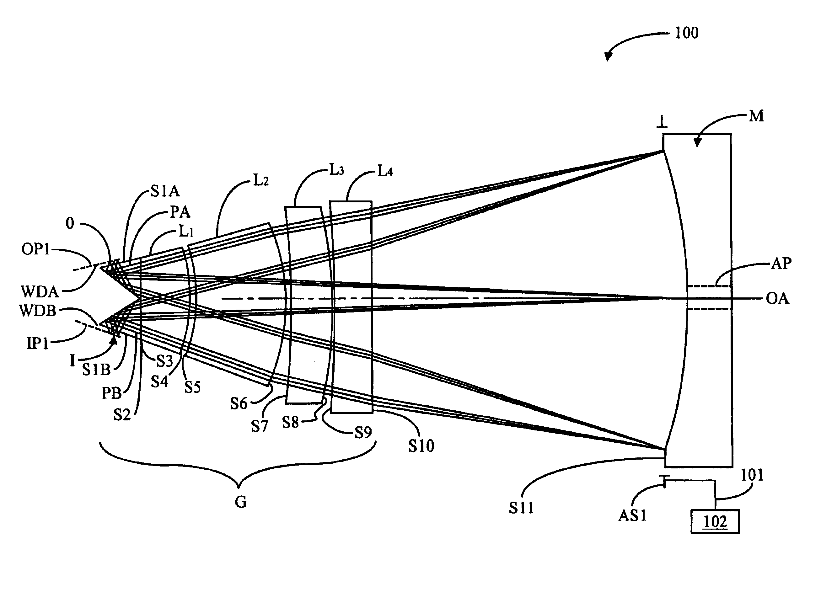
While the projection optical system of the present invention is described in conjunction with the optical design layout shown in FIG. 3, it will be understood that it is not intended to limit the invention to this design form, but also intended to cover alternatives, modifications and equivalents as may be included within the spirit and scope of the invention as defined and described in connection with particular design examples having the optical prescriptions shown in Tables 1-7, and as set forth in the claims. Each of the design examples in Table 1-7, has a design form based on the general design configuration illustrated in FIG. 3.

Since projection optical system 100 of the present invention is completely symmetric with respect to aperture stop AS1 at mirror M, the optical prescriptions in accompanying Tables 1-7 include only values of the optical specifications from object plane OP1 to the concave mirror M.

In Tables 1-7, a positive radius indicates the center of curvature is to ...


PUM


Abstract

A 1X projection optical system for deep ultra-violet (DUV) photolithography is disclosed. The optical system is a modified Dyson system capable of imaging a relatively large field at high numerical apertures at DUV wavelengths. The optical system includes a lens group having first and second prisms and four lenses having a positive-negative-positive negative arrangement as arranged in order from the prisms toward the mirror. A projection photolithography system that employs the projection optical system of the invention is also disclosed.

Description

BACKGROUND OF THE INVENTION1. Field of the InventionThe present invention relates to optical projection systems, and in particular to deep ultra-violet, large-field unit-magnification projection optical systems.2. Description of the Prior ArtPhotolithography is presently employed not only in sub-micron resolution integrated circuit (IC) manufacturing, but also to an increasing degree in advanced wafer-level IC packaging as well as in semiconductor, microelectromechanical systems (MEMS), nanotechnology (i.e., forming nanoscale structures and devices), and other is applications.The present invention, as described in the Detailed Description of the Invention section below, is related to the optical system described in U.S. Pat. No. 4,391,494 (hereinafter, “the '494 patent” Issued on Jul. 5, 1983 to Ronald S. Hershel and assigned to General Signal Corporation, which patent is hereby incorporated by reference. In addition, the present invention as described below is also related to the o...

Claims


Application Information

Patent Timeline
IPC IPC(8): G02B17/00G02B13/14G03B27/54G02B27/28G03B21/14H04B10/00G02B17/08G03F7/20
CPCG02B17/008G02B17/08G03F7/70225G02B17/0892G02B17/0852
Inventor MERCADO, ROMEO I.ZHANG, SHIYU
Owner VEECO INSTR
Why Eureka
Try Eureka