Foil-enveloped evacuated thermal insulation elements

a technology of thermal insulation elements and foils, which is applied in the direction of pipe protection by thermal insulation, packaging, building components, etc., can solve the problems of premature reduction of thermal insulation properties to levels, increased stress on foils, and reduced internal vacuum li

Inactive Publication Date: 2005-03-08
VA Q TEC AG
View PDF2 Cites 35 Cited by
  • Summary
  • Abstract
  • Description
  • Claims
  • Application Information

AI Technical Summary

Benefits of technology

teristics, details, advantages and effects of the invention arise from the following description of preferred embodiments of the invention and with reference to the drawing, whereby
FIG. 1 shows a schematic representation of a plant for the manufacture of thermal insulation elements in accordance with the invent

Problems solved by technology

A limiting condition in all these applications, as well as others, is that the thermal insulation elements which can be used for this purpose should have as small a volume as possible, in view of a wide range of considerations, especially aesthetic and practical ones.
Although the use of styrofoam panels, for example, may reduce heat loss through the exterior walls of buildings, they do not do so to the desired extent, since the usual panel thickness of 5 cm, for example, is not sufficient for this purpose.
Whereas the foil substrate is elastic and therefore more or less stretchable, the metallic coating, which is usually only a few nanometres thick, cannot withstand pronounced stretching or other deformation and in such cases develops microscopic cracks which cannot be discerned with the naked eye but which significantly reduce the life of the internal vacuum and thus prematurely reduce the thermal insul

Method used


Image

  • Foil-enveloped evacuated thermal insulation elements
  • Foil-enveloped evacuated thermal insulation elements
  • Foil-enveloped evacuated thermal insulation elements

Examples


Embodiment Construction

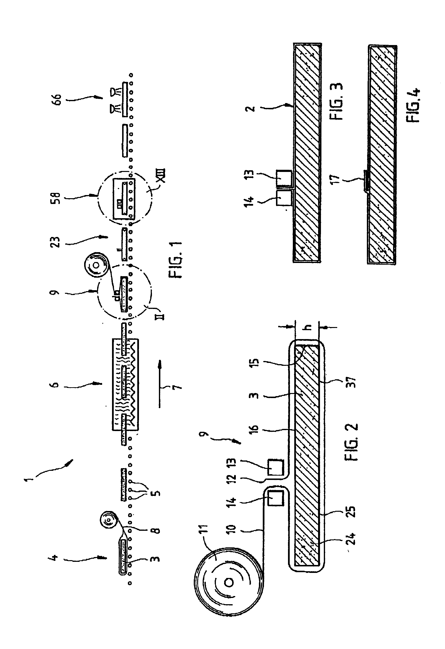
FIG. 1 shows a schematic view of a production line for the manufacture of thermal insulation elements 2 of the panel-formed shape shown in plan view in FIG. 14 for example, in accordance with the invented process.

Not shown is a forming process in which a core 3 is pressed from a powder, e.g. pyrogenic silicic acid, or foamed from a plastic, for example polystyrene or polyurethane. This blank core can already have the desired form of the thermal insulation element 2 which is to be manufactured or can be further processed for this purpose, e.g. by sawing or cutting. The blank cores should correspond as exactly as possible to the desired form of the final thermal insulation element 2, although a shrinkage during the evacuation phase on the order of around 5% can be compensated by means of corresponding overdimensioning.

The blank cores 3 are taken from an intermediate store and first enveloped in a felt in a first processing station 4. This has the function of holding back any particles...


PUM

PropertyMeasurementUnit
Areaaaaaaaaaaa
Thermal propertiesaaaaaaaaaa

Abstract

The invention relates, on the one hand, to a prismatic, especially panel-formed thermal insulation element which is enveloped in a gas-tight foil and evacuated, whereby a stable core pre-formed from a porous material is completely enveloped in a single cut sheet of the gas-tight foil; as well as a manufacturing process for same comprising the following steps:
    • a) Manufacture of a prismatic core corresponding to the desired form of the thermal insulation element from a porous material;
    • b) Enveloping of the principal faces of this core with a single sheet of the gas-tight foil;
    • c) At least partial welding together of the foil which is drawn tight around the core along the face of the core;
    • d) Folding-in of the welded seam area of the foil against the face of the core;
    • e) Stress-free folding-together of the areas of the cut sheet of gas-tight foil projecting beyond the core, covering and in flat contact with the end surface(s) of the core;
    • f) Welding together of the folded-together areas of foil on at least one end face of the core;
    • g) Evacuation of the enveloped core;
    • h) Complete welding closed of all remaining openings in the foil under vacuum.

Description

FIELD OF THE INVENTIONThe invention relates to a flat-sided, generally prismatic, in particular parallelepipedal and / or panel-formed thermal insulation element which is enveloped in a gas-tight foil and evacuated, as well as a process for its manufacture.DESCRIPTION OF THE RELATED ARTHigh-quality thermal insulation is required in an extremely wide range of areas of application. As well as the transport of refrigerated medical samples, organs etc. in containers which are, or can be, specially manufactured for this purpose, use in the thermal insulation of buildings is, in particular, of great importance, since the primary energy requirement can be significantly reduced through good thermal insulation, which represents an important measure for compensating continually increasing heating oil prices. A limiting condition in all these applications, as well as others, is that the thermal insulation elements which can be used for this purpose should have as small a volume as possible, in v...

Claims


Application Information

Patent Timeline
IPC IPC(8): B29C63/04B29C63/02E04B1/80F16L59/06F16L59/065B29K105/04B29L31/00
CPCB29C63/04E04B1/803F16L59/065Y10T428/24256B29K2075/00B29K2105/04B29K2105/045B29K2995/0015B29K2995/0065B29K2995/0067Y02B80/12Y10S493/907Y10S493/908Y10S493/903Y10T428/24777Y10T428/2419Y10T428/238Y10T428/23Y10T428/24231Y10T428/19Y10T156/1034Y10T428/24264Y10T428/231Y10T428/239Y10T428/233B29K2025/00Y02A30/242Y02B80/10
Inventor EHRMANNTRAUT, MICHAEL E.
Owner VA Q TEC AG
Why Eureka
Try Eureka