Ion sources

a technology of ion sources and ion beams, applied in the field of plasma technology, can solve the problems of limited application in a broad range of desired ion beam processes, current available ion sources are not suited to producing the above mentioned required conditions, etc., and achieve greater and more uniform ion acceleration, improve the uniform distribution of magnetic field, and increase the magnetic field gradient

Inactive Publication Date: 2005-03-08
VEECO INSTR
View PDF13 Cites 2 Cited by
  • Summary
  • Abstract
  • Description
  • Claims
  • Application Information

AI Technical Summary

Benefits of technology

The present embodiment of the ion source provides a second pole gap forming a magnetic quadrapole lens. A closed Hall current generated in the second pole gap provides for additional ionization of the working gas and enhances the magnetic field in the first pole gap which helps to stabilize the discharge and the ion acceleration process. Also with the second gap, conditions are created for effective additional ion acceleration. This possibility is realized by selecting the appropriate geometric ratio of distances between pole pieces in both gaps, such that the interaction of internal magnetic fields generated by the closed electron drift currents and the magnetic field generated by the magnetic system of the ion source results in a net increase in magnetic field. Another advantage of the present invention is derived when a magnetically permeable end wall is used in conjunction with the four-pole (quadrapole) magnetic lens. In this case, an open magnetic circuit is created which results in an increase in magnetic field gradient in the first pole gap and improves the uniformity of the distribution of the magnetic field along the exit hole of the ion source which provides greater and more uniform ion acceleration.
is derived when a magnetically permeable end wall is used in conjunction with the four-pole (quadrapole) magnetic lens. In this case, an open magnetic circuit is created which results in an increase in magnetic field gradient in the first pole gap and improves the uniformity of the distribution of the magnetic field along the exit hole of the ion source which provides greater and more uniform ion acceleration.
The magnetic system may comprise permanent magnets arranged between pole pieces in the first and second pole gaps, along opposite edges of the closed loop exit hole. The magnetic field induction vectors in the permanent magnets arranged in the vicinity of the opposite edges of the exit hole are oriented parallel to the direction of ion emission and have opposite polarity. The present embodiment intensifies the magnetic field and improves the uniformity of distribution of magnetic field strength in the pole gaps.
It should be noted that only one permanent magnet might be used as a magnetomotive force source in the ion source executed in accordance with an independent claim of the invention. To generate a magnetic field in two successive pole gaps, the single magnetomotive force source may be made of closed loop-shape type and may be arranged along the outer edge of the exit hole (as shown in FIG. 4A of the patent U.S. Pat. No. 4,277,304), or, alternatively, it may be made of open-shape type and arranged along the inner edge of the exit hole (as shown in FIG. 8A of the patent U.S. Pat. No. 4,277,304).
A preferred embodiment of the invention may use an internal magnetic flux conducting jumper for connecting the opposite end walls of the enclosure. In this case, the anode of closed loop-shape conforming that of the exit hole is formed and arranged around the internal magnetic flux conducting jumper of the enclosure.
It is advantageous to use an additional permanent magnet as an internal magnetic flux conducting jumper. The magnetic field induction vector of the additional magnet is oriented parallel to the direction of ion emission and has opposite polarity with respect to the magnetic field induction vector of the magnet arranged opposite to the additional magnet, on the outside of the enclosure.

Problems solved by technology

Thus, the outside pole pieces of the prior art ion source are designed only for concentrating the magnetic flux within the cavity of the magnetic circuit enclosure and do not serve as magnetic elements defining an additional magnetic working gap.
However, the patent U.S. Pat. No. 4,277,304 does not indicate specific conditions determining the distribution of the magnetic field in the magnetic lens, which forms at the exit hole of the ion source and serves to generate an ion beam.
Hence, it is unjustified to draw the conclusion of a possible effect of the second magnetic gap of the magnetic lens used in the prior art device upon the ionization and the ion acceleration processes.
On the whole, currently available ion sources are not suited to producing the above mentioned required conditions and, because of this, have limited possibility for application in a broad range of desired ion beam processes.

Method used


Image

  • Ion sources
  • Ion sources
  • Ion sources

Examples


first embodiment

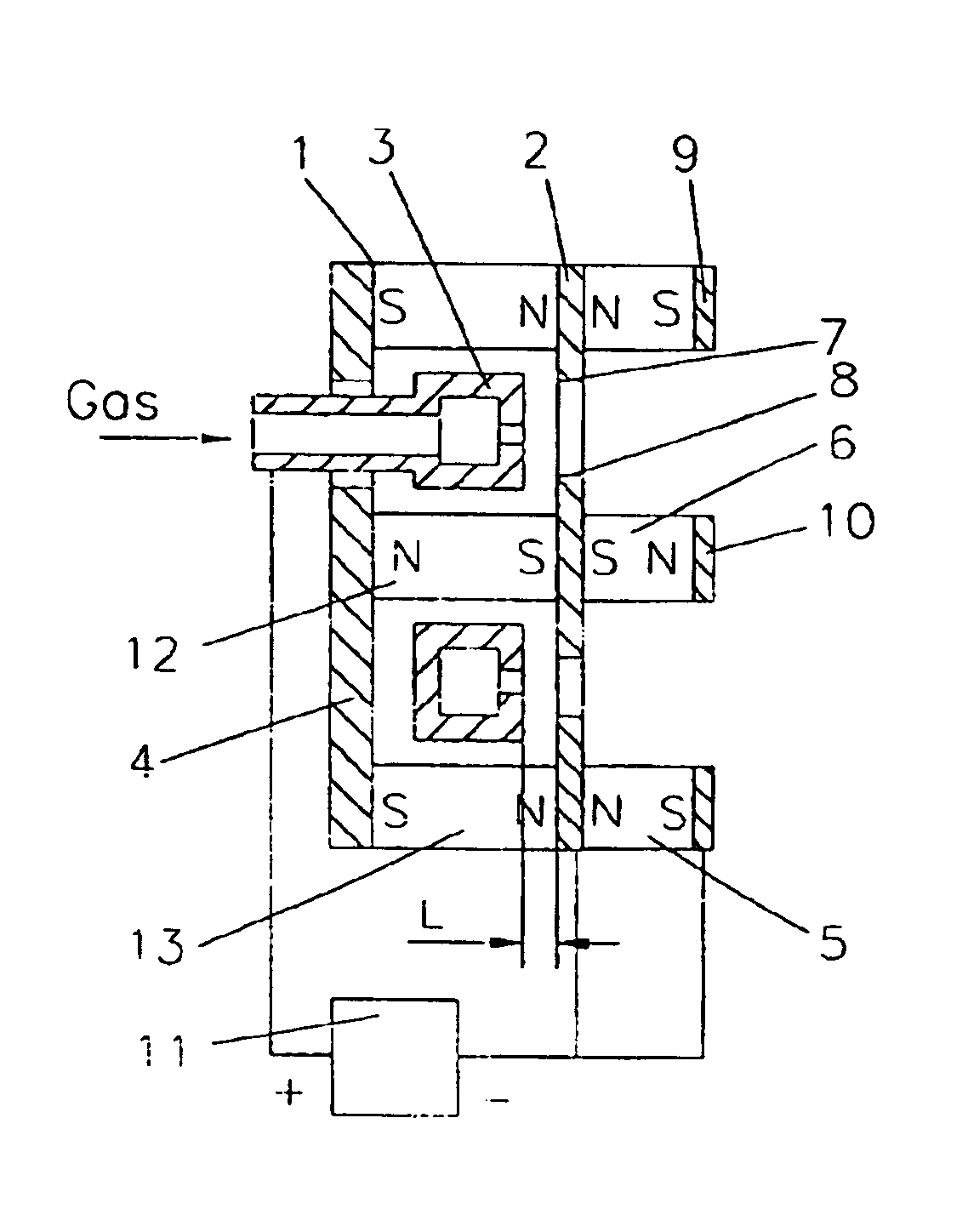
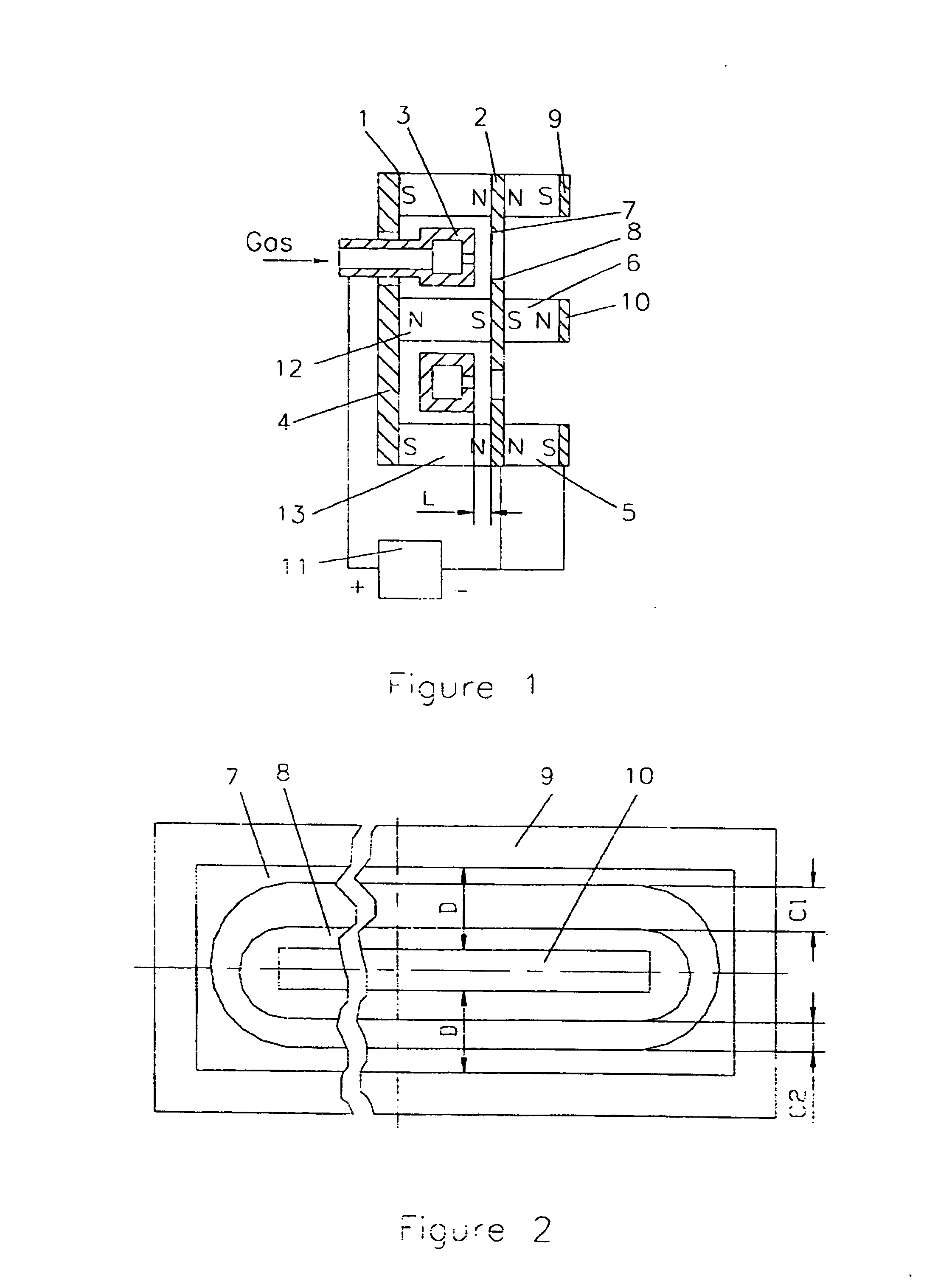
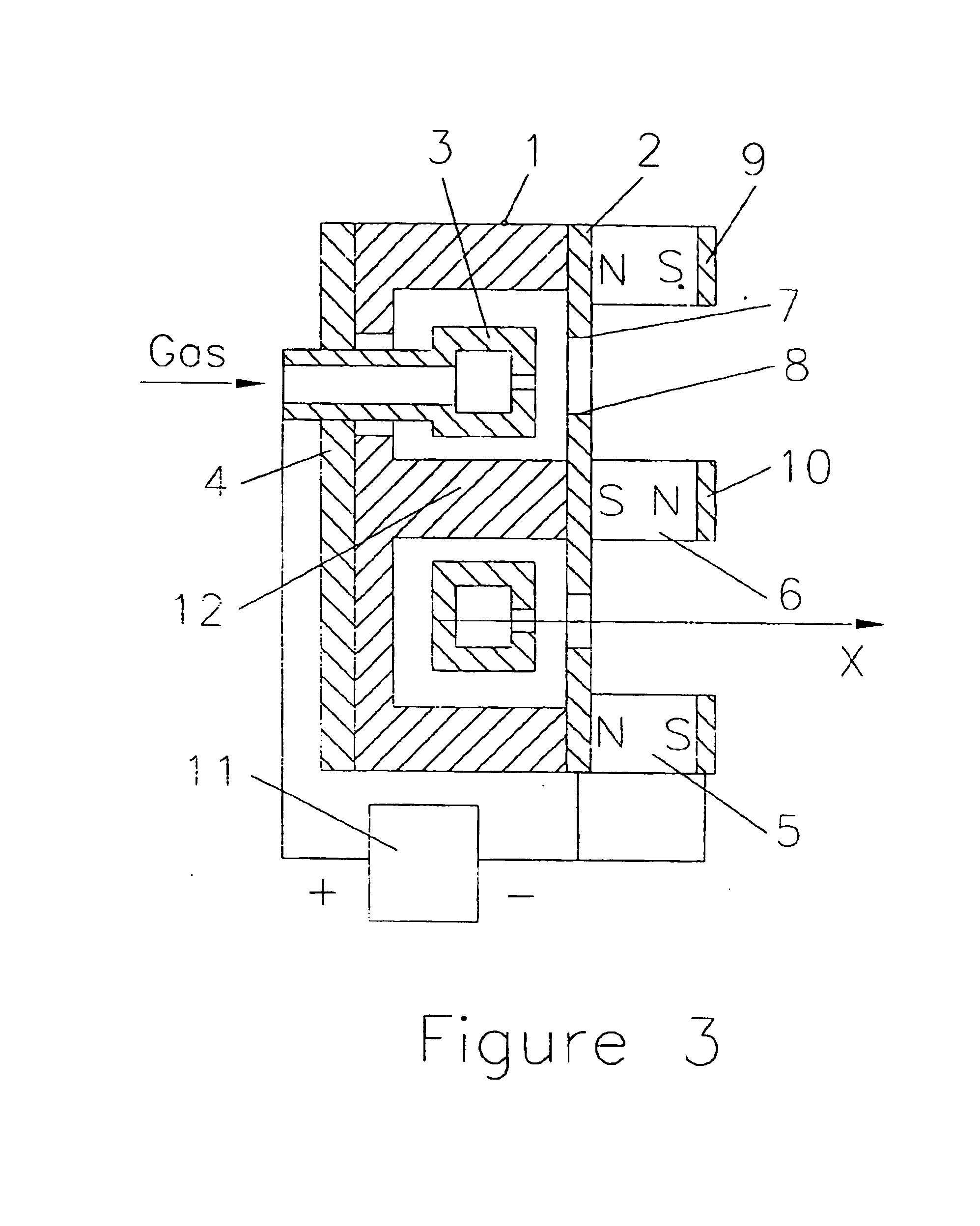
The ion source, in accordance with the invention, (see FIGS. 1 through 3) is comprised of an enclosure 1 having an end wall 2 provided with a closed loop exit hole for ion emission made in the form of an elongated closed loop emission slot. An anode 3 is arranged inside enclosure 1 opposite to the emission slot. The ion source is further provided with a gas distributor, which may be structurally combined with anode 3. The magnetic system of the device is comprised of magnetomotive force sources, pole pieces and magnetically permeable wall 4 of enclosure 1. The magnetomotive force sources are made in the form of permanent magnets 5 and 6 arranged on the outside of enclosure 1 along edges of the closed loop emission slot. End wall 2 is manufactured of magnetically permeable material and is also a part of the magnetic system. The parts of end wall 2, separated by the closed loop emission slot, function as pole pieces 7 and 8 defining the first pole gap downstream in the ion emission di...

second embodiment

The extended cylindroid beam ion source made according to the invention (see FIGS. 9 through 12) is comprised of an enclosure 18 with an end wall 19 provided with a closed loop slot-shaped exit hole for ion emission. An anode 20 is located inside enclosure 18 opposite to the closed loop ion emission hole. The ion source is further comprised of a gas distributor which may be structurally combined with anode 20. The magnetic system of the device includes magnetomotive force sources made in the form of permanent magnets 21,22 and pole pieces 23,24 and 25,26.

The parts of end wall 19 separated by the closed loop emission hole serve as pole pieces 23 and 24 which define a first pole gap downstream in the direction of ion emission. Pole pieces 25 and 26 define a second pole gap opposite to the first pole gap in the direction of ion emission. Permanent magnets 21 and 22 are arranged between pole pieces 23,25 and 24,26, respectively. The polarity of magnets 21 and 22 (N-S and S-N) is selecte...


PUM


Abstract

A closed loop exit hole is formed in a magnetically permeable end wall (2) of an enclosure (1) of a closed electron drift ion source. Parts of this end wall separated by the exit hole serve as pole pieces (7 and 8) of the magnetic system and define the first pole gap. The magnetic system includes pole pieces (9 and 10), which define the second pole gap made in the form of a closed loop exit hole and arranged along the direction of ion emission. Magnetomotive force sources (5 and 6) are located in space between two groups of magnetic terminals. The ratio of width of each pole gap and distance between pole pieces of the first (7 and 8) and second (9 and 10) magnetic gaps along the direction of ion emission is not less than 0.05.The invention allows the intensity of the generated ion beam and the energy of ions to be increased, and this is provided by the homogeneous distribution of ion current density across the ion beam section.

Description

FIELD OF THE INVENTIONThe invention relates to plasma technology and, more particularly, it pertains to plasma devices designed for the generation of intensive ion beams, including extended cylindroid beams that may be used in ion beam technologies for modifying article surfaces and for sputter deposition of coatings onto article surfaces.BACKGROUND OF THE INVENTIONCurrently available are various types of ion sources adapted for the generation of ion beams including closed electron drift (or closed Hall current) ion sources. Such ion sources are subdivided into two types: ion sources with an extended acceleration zone comprising a dielectric channel (for example, European application EP 0 541 309 A1, IPC H05H1 / 54, F03H 1 / 100, published May 12, 1993), and ion sources with a short acceleration zone (for example, the patent U.S. Pat. No. 4,122,347, IPC H01J 27 / 00, published Sep. 24, 1978), which are also referred to as anode layer ion sources. The second type of closed electron drift i...

Claims


Application Information

Patent Timeline
Patent Type & Authority Patents(United States)
IPC IPC(8): H01J27/18H01J27/16H05H1/54F03H1/00H01J27/02
CPCH01J27/143
Inventor ALEKSEEV, VALERY V.ZELENKOV, VSEVOLOD V.KRIVORUCHKO, MARK M.KEEM, JOHN E.
Owner VEECO INSTR
Why Eureka
Try Eureka