
Apparatus of plural charged particle beams with multi-axis magnetic lens

a multi-axis, charged particle technology, applied in the direction of magnetic discharge control, material analysis using wave/particle radiation, instruments, etc., can solve the problems of fundamentally limited spatial resolution of optical inspection tools, incompetence, and the inability to achieve the inspection speed of electron beam inspection tools, so as to achieve higher spatial resolution, lower aberrations and radiation damage on specimens

Active Publication Date: 2012-06-14
ASML NETHERLANDS BV
View PDF3 Cites 11 Cited by
  • Summary
  • Abstract
  • Description
  • Claims
  • Application Information

AI Technical Summary

Benefits of technology

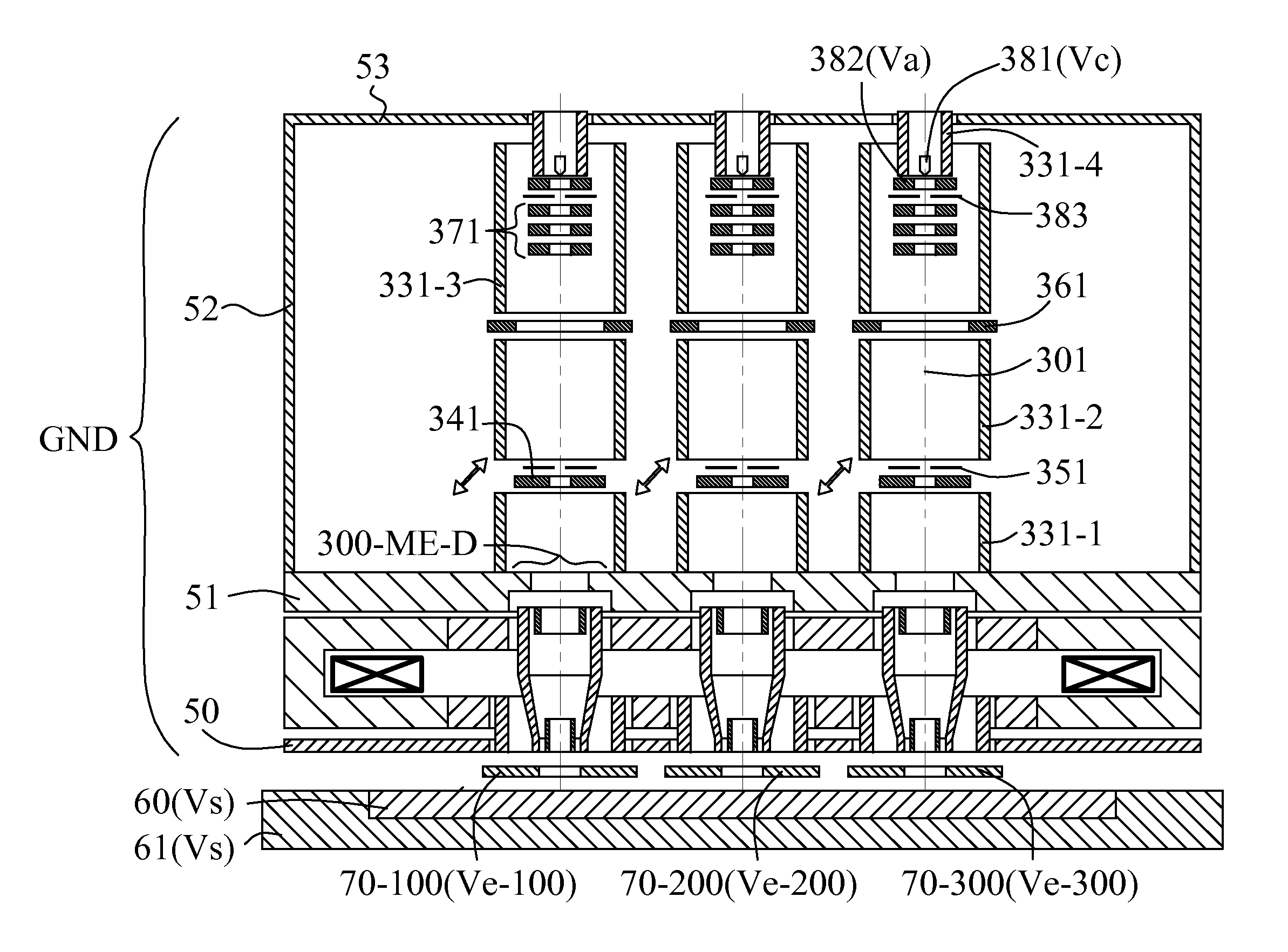
The invention is a multi-axis electron apparatus that uses a plurality of electron beams to inspect a specimen in parallel. The apparatus includes a multi-axis magnetic immersion objective lens and a multi-axis electrostatic immersion objective lens, which work together to focus electron beams with lower aberrations and lower radiation damage on the specimen. The apparatus also includes deflection scanning and compensation units to scan and compensate for the effect of residual non-axisymmetric transverse field components. The technical effects of this invention include higher spatial resolution and higher throughput than previous technologies, especially in semiconductor yield management.

Problems solved by technology

The spatial resolution of an optical inspection tool is fundamentally limited by its larger wave diffraction spot because an optical wavelength is much longer than that of an electron beam.
As critical dimensions of patterns on a wafer and a mask are required to become smaller and smaller, it is becoming incompetent.
However, the throughput or called as inspection speed of an electron beam inspection tool is fundamentally limited by electron interaction or called as Coulomb Effect.
As inspecting full wafer or full mask is becoming necessary, increasing its throughput is becoming a key issue.
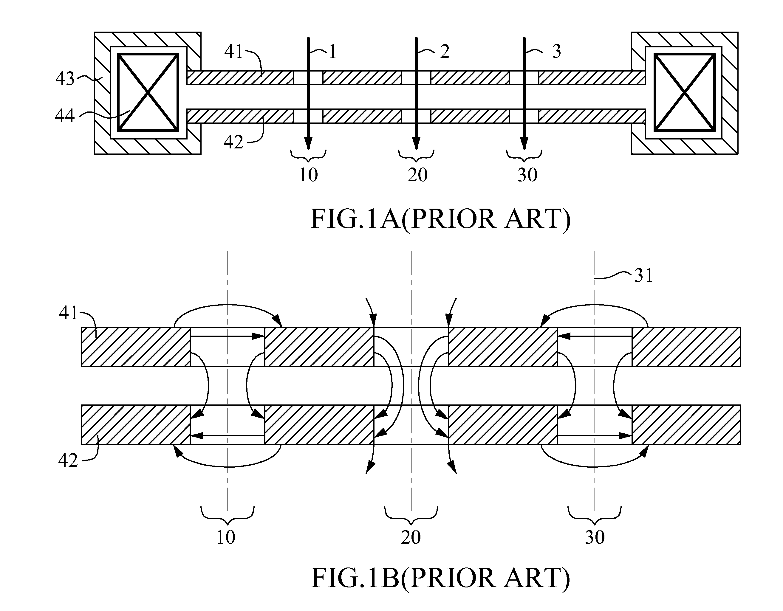
Comparing with a conventional single-axis magnetic lens, one main problem of this multi-axis magnetic lens is the magnetic field distribution of each sub-lens degenerates from axial symmetry to rotation symmetry and / or n-fold symmetry (FIG. 1B).
Another main problem of this multi-axis magnetic lens is the round lens field of the center sub-lens 20 is a little different from those of the peripheral sub-lenses 10 and 30.
These previous methods were either making the magnetic conductor plate become larger, the multi-axis magnetic lens system bulky, or making it complicated.
Nevertheless, it is well known that, compared with a radial-gap magnetic lens (having a radial magnetic circuit gap), this type of magnetic lens generates larger aberrations which damages spatial resolution, but requires small coil excitation (product of coil turns and coil current) which abates the issue of system overheat.

Method used


Image

  • Apparatus of plural charged particle beams with multi-axis magnetic lens
  • Apparatus of plural charged particle beams with multi-axis magnetic lens
  • Apparatus of plural charged particle beams with multi-axis magnetic lens

Examples


Embodiment Construction

[0047]Reference will now be made in detail to specific embodiments of the invention. Examples of these embodiments are illustrated in accompanying drawings. While the invention will be described in conjunction with these specific embodiments, it will be understood that it is not intended to limit the invention to these embodiments. On the contrary, it is intended to cover alternatives, modifications, and equivalents as may be included within the spirit and scope of the invention as defined by the appended claims. In the following description, numerous specific details are set forth in order to provide a thorough understanding of the present invention. The present invention may be practiced without some or all of these specific details. In other instances, well known process operations are not described in detail in order not to unnecessarily obscure the present invention.

[0048]In this invention, all terms relating to through round holes, circular openings, or circular orifices mean ...


PUM

PropertyMeasurementUnit
energyaaaaaaaaaa
magnetic fluxaaaaaaaaaa
dipole fieldaaaaaaaaaa

Abstract

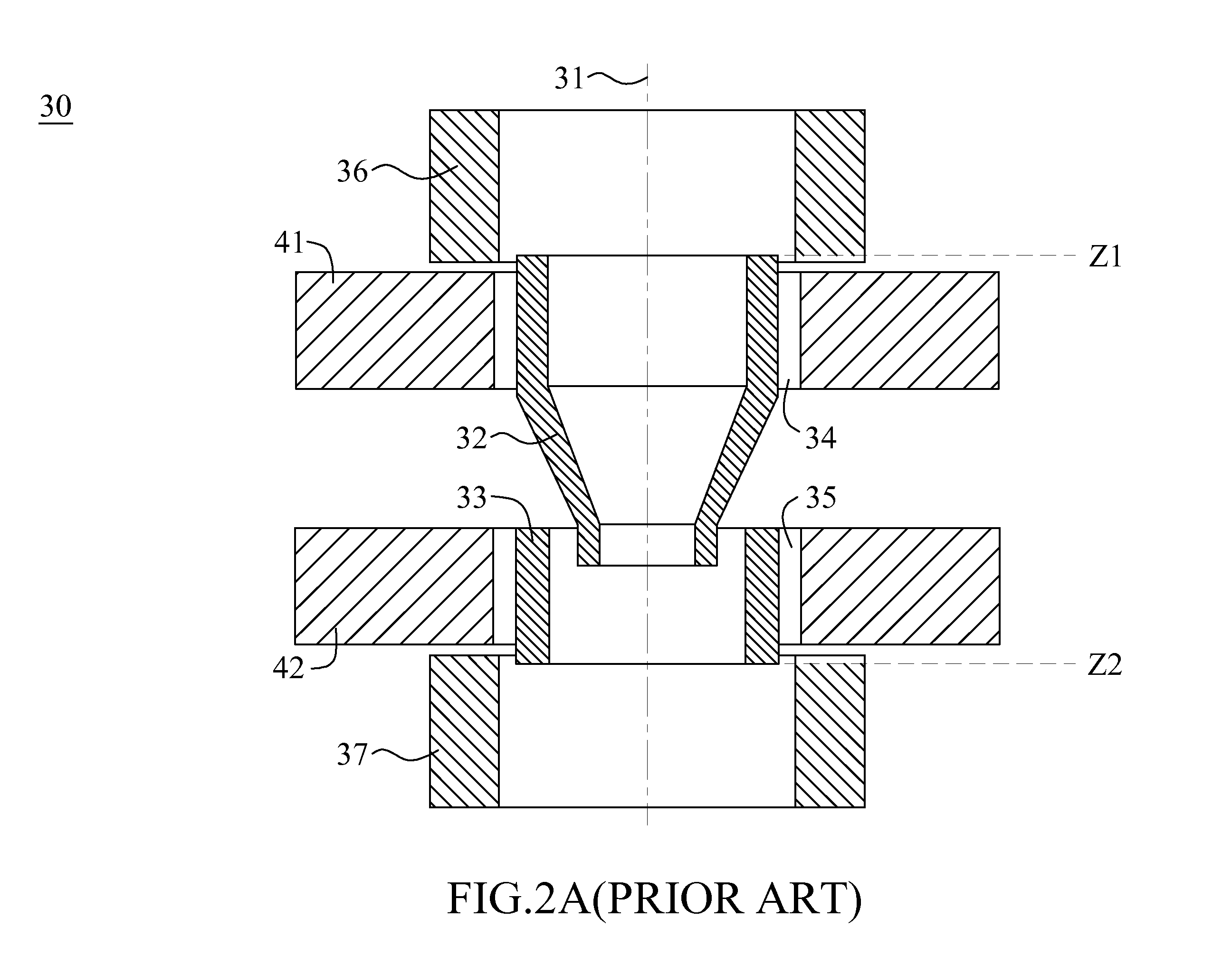
An apparatus basically uses a simple and compact multi-axis magnetic lens to focus each of a plurality of charged particle beams on sample surface at the same time. In each sub-lens module of the multi-axis magnetic lens, two magnetic rings are respectively inserted into upper and lower holes with non-magnetic radial gap. Each gap size is small enough to keep a sufficient magnetic coupling and large enough to get a sufficient axial symmetry of magnetic scale potential distribution in the space near to its optical axis. This method eliminates the non-axisymmetric transverse field in each sub-lens and the round lens field difference among all sub-lenses at the same time; both exist inherently in a conventional multi-axis magnetic lens. In the apparatus, some additional magnetic shielding measures such as magnetic shielding tubes, plates and house are used to eliminate the non-axisymmetric transverse field on the charged particle path from each charged particle source to the entrance of each sub-lens and from the exit of each sub-lens to the sample surface.

Description

CROSS-REFERENCE TO RELATED APPLICATIONS[0001]This application relates to co-pending U.S. application Ser. No. 12 / 636,007, filed Dec. 11, 2009 and entitled “A MULTI-AXIS MAGNETIC LENS.” The foregoing application is commonly assigned and the entire contents are expressly incorporated herein by reference.FIELD OF THE INVENTION[0002]The present invention relates to a multi-axis magnetic immersion objective lens. More specifically, it relates to a multi-axis charged particle apparatus for obtaining a high spatial resolution and a high throughput in defect inspection of semiconductor wafer and mask.BACKGROUND OF THE INVENTION[0003]Defect inspection of semiconductor wafer and mask in IC manufacturing is an accepted significant production process for yield enhancement. The information obtained from a wafer defect inspection tool can be used to flag defective dies for repair, or improve wafer processing parameters. There are two main kinds of inspection tools used for defect inspection in se...

Claims


Application Information

Patent Timeline
Patent Type & Authority Applications(United States)
IPC IPC(8): G01N23/04
CPCG01N23/2251G01N2223/6116H01J2237/2817H01J37/141G01N2223/646
Inventor CHEN, ZHONGWEIREN, WEIMINGKANAI, KENICHILIU, XUEDONG
Owner ASML NETHERLANDS BV
Learn More