Magnetic disk drive and voice coil motor drive circuit

Inactive Publication Date: 2005-03-08
HITACHI GLOBAL STORAGE TECH JAPAN LTD
View PDF6 Cites 15 Cited by
  • Summary
  • Abstract
  • Description
  • Claims
  • Application Information

AI Technical Summary

Benefits of technology

With the foregoing in view, it is an object of the present invention to provide a back electromotive force sensor that can detect high quality back electromotive force signals, that is back electromotive force signals that can be detected without any problem associated with the transient response caused by the above differential item and without affecting fast changes in current in a fast control sample period.
To fulfill the foregoing object, the present invention provides a positioning device for driving and positioning an actuator using a VCM, with the following means for detecting the back electromotive force produced in the VCM coil: a first circuit that detects the terminal voltage of a VCM coil and outputs a band-limited signal that is a constant multiple of that value; a second circuit that detects the drive current for the voice coil motor and that outputs a voltage signal that is proportional to the above drive current; and a computation circuit that determines the difference between the output of the above first circuit and the output of the above second circuit. The first circuit has the effect of eliminating the item that is proportional to the VCM coil current differential, which was problematic in conventional methods.
Also, the present invention is configured so that the first circuit is a primary analog low pass filter with a time constant that is substantially equal to the ratio between the inductance and resistance of the VCM coil. This configuration simplifies detection and calculation of back electromotive force.
The band limiting is achieved in the first circuit by a primary digital low pass filter that is configured so that its time constant is substantially equal to the ratio between the inductance and resistance of the VCM coil. This configuration simplifies detection and calculation of back electromotive force.
In the low pass filter, the resistor that prescribes the filter gain and the capacitor that prescribes the filter time constant are located outside the IC chip. The second circuit and the computation circuit are provided as coefficient amplifiers in which operational amplifiers are used. The resistor that prescribes the gain of these coefficient amplifiers is located outside the IC chip. This configuration enables great scope for adjustment of filter and coefficient amplifier gain and for adjustment of the time constants for the above filters.

Problems solved by technology

However, restrictions on the control sample period in conventional back electromotive force sensors narrow the range of use for back electromotive force signals.
Therefore, conventional back electromotive force sensors with a sampling period of approximately 700 μs could not be used as a speed signal during normal positioning operations.
The first circuit has the effect of eliminating the item that is proportional to the VCM coil current differential, which was problematic in conventional methods.

Method used


Image

  • Magnetic disk drive and voice coil motor drive circuit
  • Magnetic disk drive and voice coil motor drive circuit
  • Magnetic disk drive and voice coil motor drive circuit

Examples


first embodiment

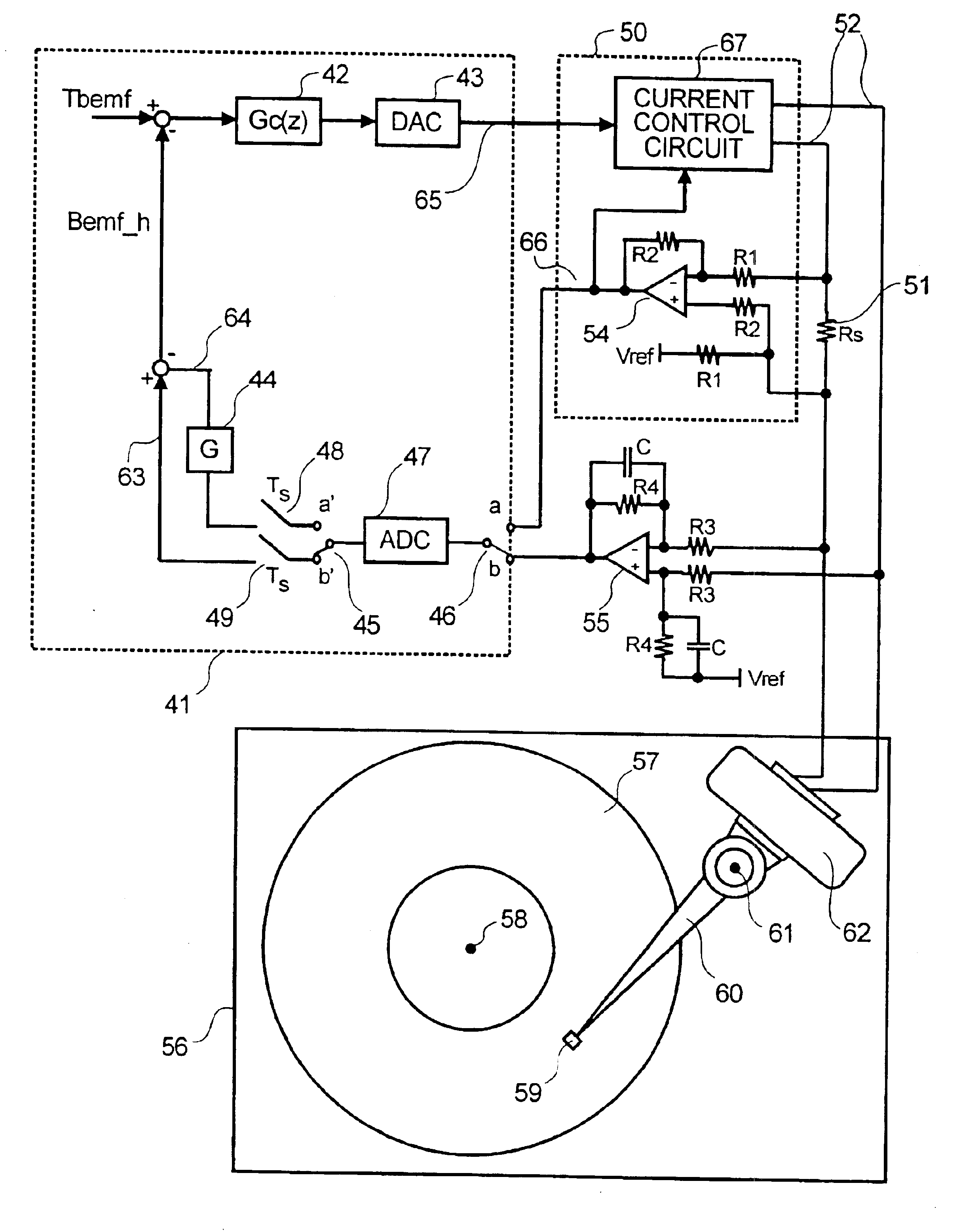
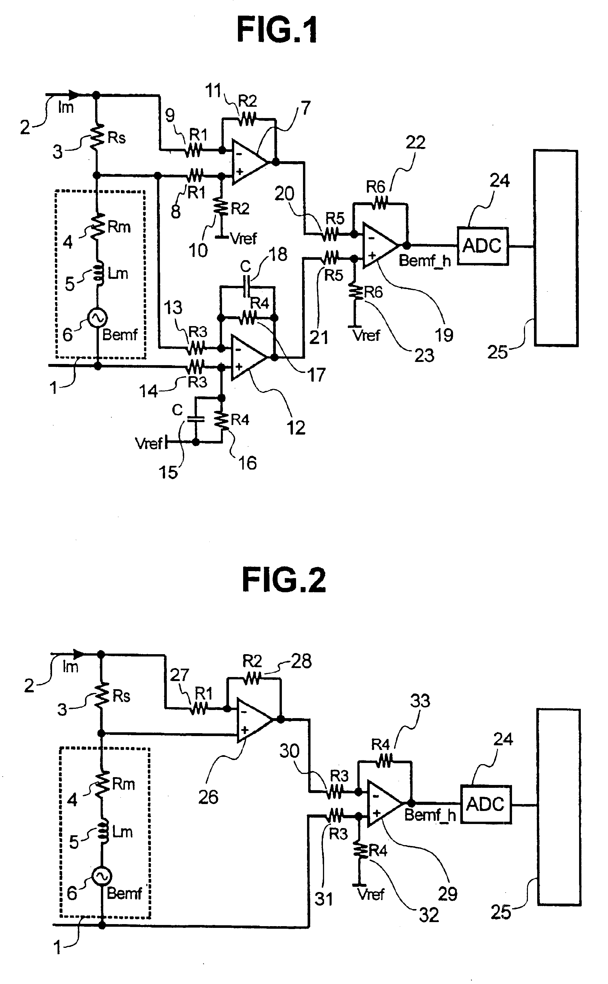
FIG. 1 shows a back electromotive force sensor according to the present invention. As shown in the drawing, the VCM coil 1 can be modeled as a series connection of three elements: resistor 4 of resistance Rm; inductor 5 of inductance Lm; and the back electromotive force 6, which should be detected with them. The VCM coil 1 is connected in series with a current sensing resistor 3 to a driver circuit that is not shown. The current 2 is controlled by this driver circuit.

Low pass filters, each comprising an operational amplifier 12, resistors 13, 14, 16, and 17, and capacitors 15 and 18, are connected across both ends of the VCM coil 2. These low pass filters are an example of a first circuit means in accordance with the present invention. These low pass filters are primary low pass filters, wherein the gain AI=R4 / R3 and the filter time constant Tm=C×R4. Gain AI is selected so that the output value for the operational amplifier 12 is not saturated even when the maximum voltage that can ...

second embodiment

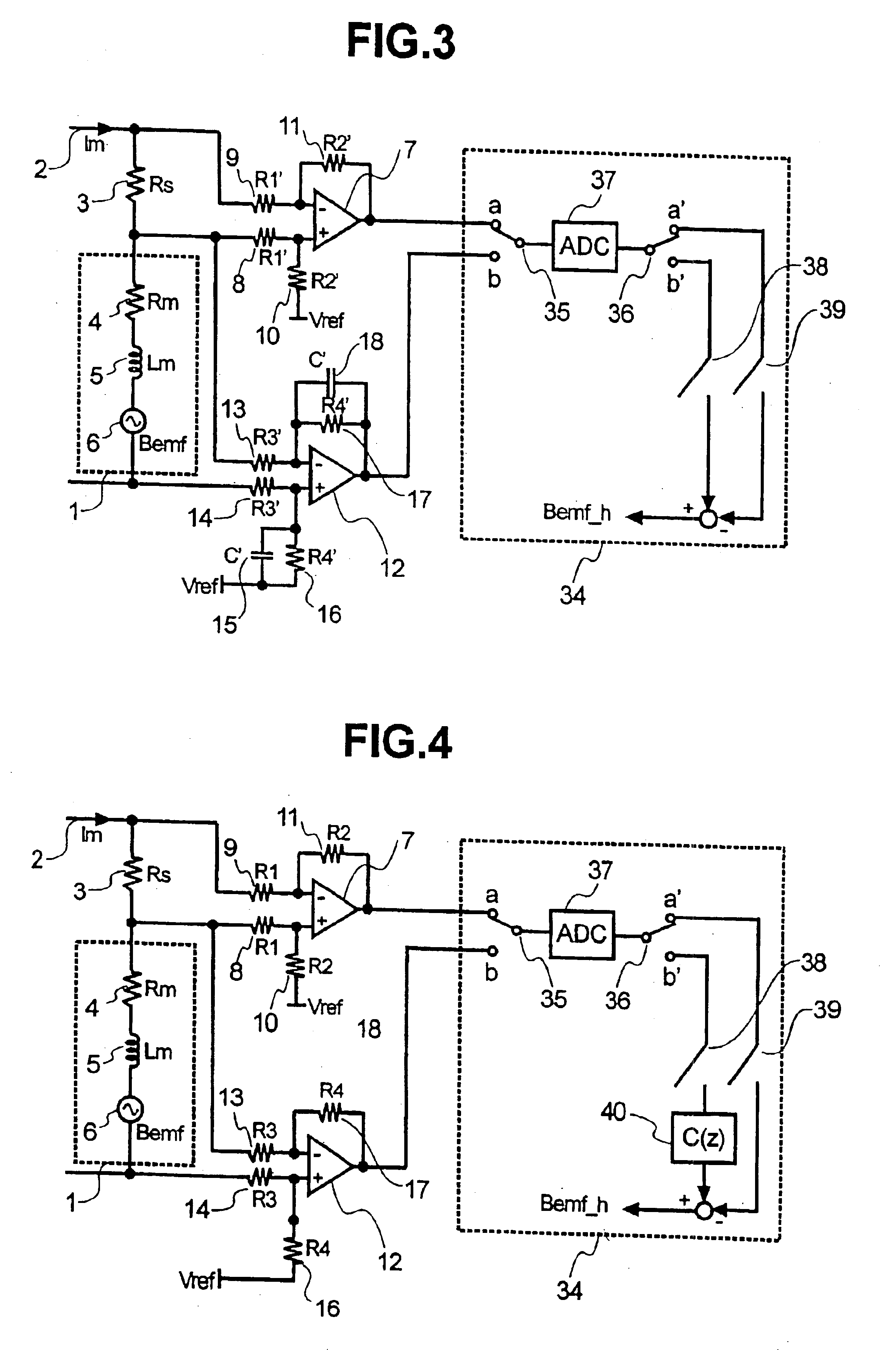
FIG. 3 shows a back electromotive force sensor according to the present invention. In this example, the circuit computations carried out in the first aspect of the embodiment using operational amplifier 19 are carried out as numeric computations within a microcomputer. Below, the elements from which this second aspect of the embodiment are configured will be explained.

In FIG. 3, elements that are also found in FIG. 1 are identified with the same symbols. As in the first embodiment, primary low pass filters, with a gain AI′=R4′ / R3′ and a filter time constant Tm=C′×R4′, each comprising an operational amplifier 12. resistors 13, 14, 16, and 17, and capacitors 15 and 18, are connected across both ends of the VCM coil 2. These low pass filters are an example of the first circuit means used in accordance with the present invention. Gain AI′ and reference voltage Vref are selected so that they do not exceed the input range of the AD converter 37 in the microcomputer 34 even when the maximu...


PUM


Abstract

A magnetic disk drive that drives and positions an actuator using a voice coil motor, includes a current sensing resistor connected in series to a terminal on current input side of the voice coil motor, a first operational amplifier and a second operational amplifier. The magnetic disk drive further includes one of a third operational amplifier and a microcomputer.

Description

BACKGROUND OF THE INVENTIONThe present invention relates to a magnetic disk drive that implements positioning of a magnetic head using a voice coil motor (abbreviated to VCM hereinafter), and to a speed control method using the back electromotive force of a VCM.As disclosed in JP-A 11-25625, a VCM back electromotive force sensor is used for speed control during loading and unloading of the magnetic head in a magnetic disk drive system that has a mechanism that moves the magnetic head into an evacuation area on the disk surface when it is not operating, and this is called a load-unload system.In a well-known method of detecting back electromotive force, a voltage that is proportional to the VCM drive current is subtracted from the VCM coil terminal voltage, as shown in FIG. 2. In this figure, the VCM coil 1 can be modeled, as shown in the diagram, as a series connection of three elements: resistor 4 of resistance value Rm; an inductance 5 of inductance value Lm; and a back electromot...

Claims


Application Information

Patent Timeline
IPC IPC(8): G11B21/02G11B5/55G11B21/08
CPCG11B21/02G11B5/5526G11B5/553G11B5/5547
Inventor ABE, JIROHAMADA, YOSUKE
Owner HITACHI GLOBAL STORAGE TECH JAPAN LTD
Why Eureka
Try Eureka