

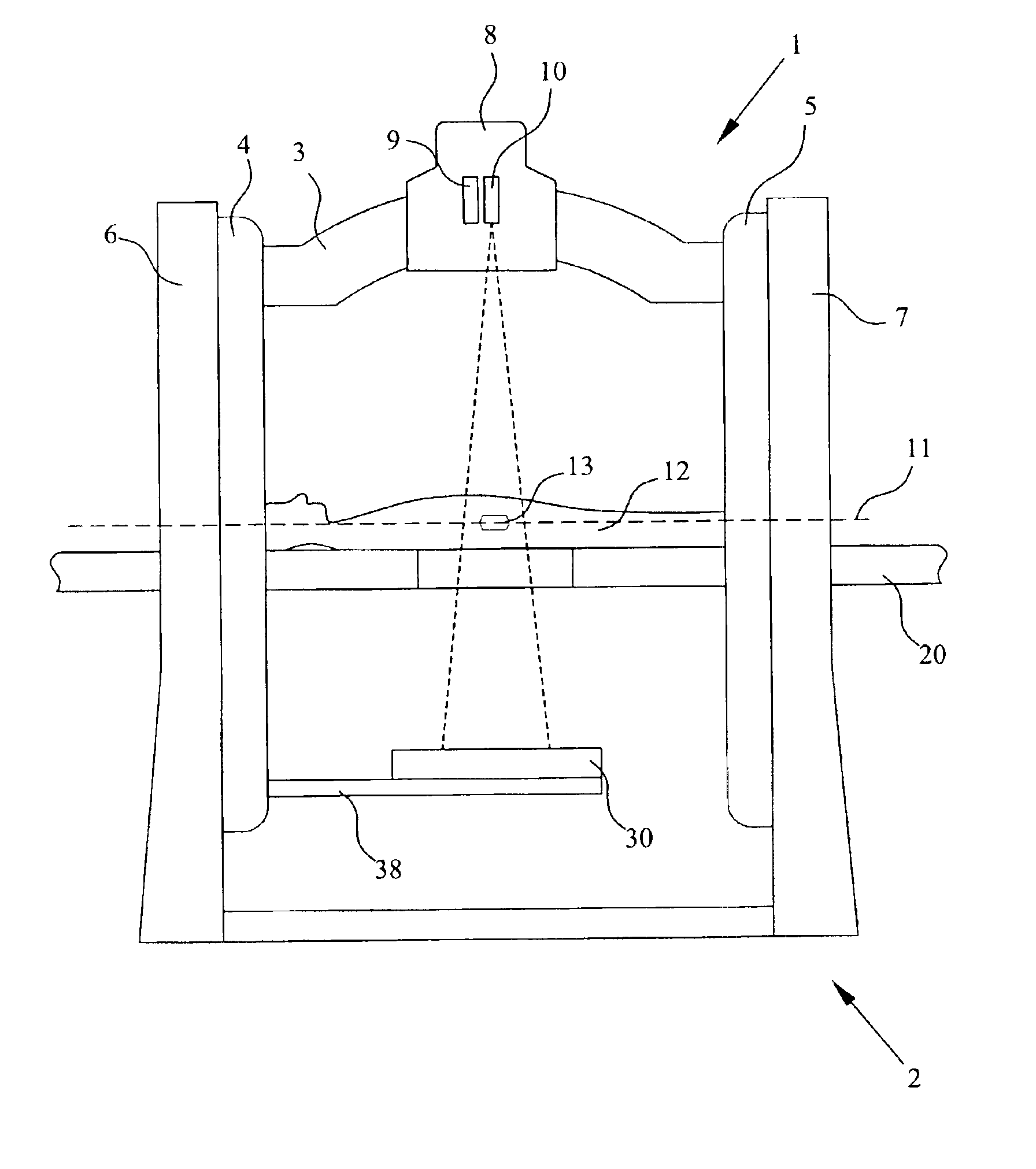
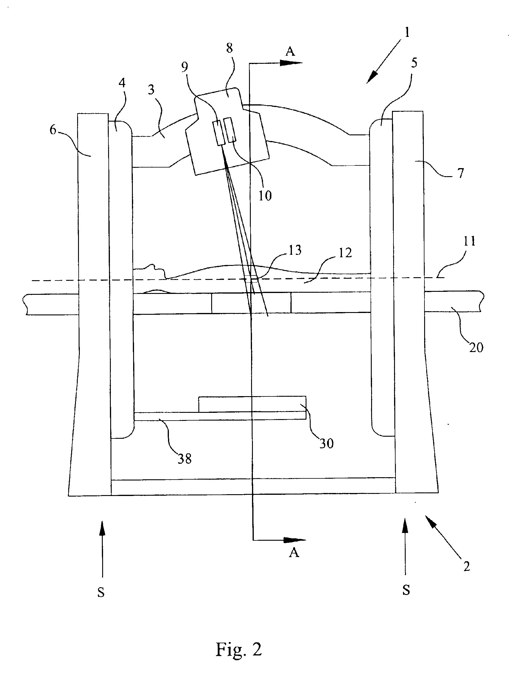
Radiation system with inner and outer gantry parts
a radiation system and gantry technology, applied in the field of radiation systems, can solve the problems of affecting the treatment effect, the spatial relationship between the target volume and the reference point, the shape and size of the tumor may change, and the radiation dose may actually partially or completely miss the target volume, instead of hitting adjacent tissues and organs, and achieves stable gantry design. , the effect of reducing the total cost and high resolution and accuracy
- Summary
- Abstract
- Description
- Claims
- Application Information
AI Technical Summary
Benefits of technology
Problems solved by technology
Method used
Image

Examples
Embodiment Construction
Throughout the drawings, the same reference characters will be used for corresponding or similar elements.
The invention is generally applicable to a radiation machine. As referred to in the present description, in a radiation machine a dose package or radiation beam, such as a beam of gamma photons, electrons, neutrons, protons or heavier ions, atoms or molecules, is applied to patient. The radiation machine may be employed for curative radiation therapy, i.e. to eradicate a tumor or palliative radiation therapy, where the aim is generally to improve quality of life of the patient by maintaining local tumor control, relieve a symptom or prevent or delay an impending symptom, and not primarily to eradicate the tumor. Yet another application of a radiation machine may be in radiation surgery using a high-energy radiation source.
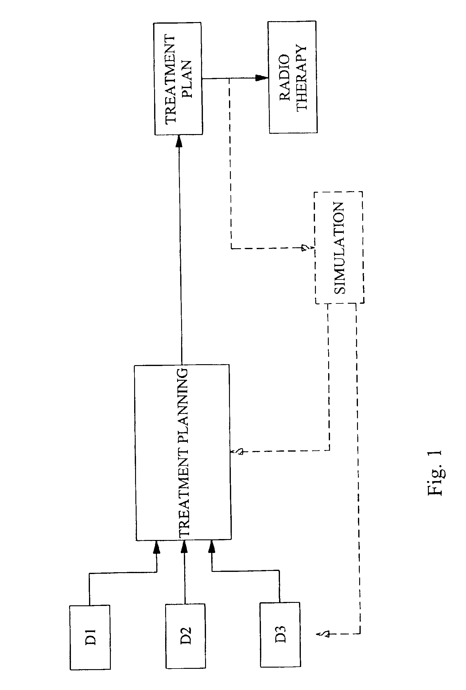
For a better understanding of the invention, it may be useful to start with a brief introduction of a radiation therapy process with reference to FIG. 1.
Genera...
PUM
 Abstract
Description
Claims
Application Information