Echo cancellation method and apparatus

a cancellation method and echo technology, applied in the field of echo cancellation methods and apparatuses, can solve the problems of delay of echo, weak coupling strength, and almost always unavoidable coupling, and achieve the effect of increasing the bandwidth of the signal and increasing the computational burden

Inactive Publication Date: 2005-03-08
INMUSIC BRANDS
View PDF6 Cites 30 Cited by
  • Summary
  • Abstract
  • Description
  • Claims
  • Application Information

AI Technical Summary

Benefits of technology

The preferred embodiment second method increases the bandwidth of the signal sent back to the far end without a large increase in computational burden. It does this by only applying the echo cancellation to the lower end of the frequency spectrum where the majority of speech energy resides (below 3 k), and relies on suppression techniques (light computational burden) for frequencies above 3 kHz.

Problems solved by technology

This coupling is almost always unavoidable.
However, the strength of the coupling is affected by the designer's setup of the room and any acoustic treatment applied to the room.
For acoustic echo both the acoustic path delay and transmission delay contribute to the delay of the echo.
However, the specific differences in the sources of echo require differences in their solutions.
This process is time consuming and very annoying to those located at the near end.
Any excessive noise will cause divergence in the filter model being formed from the actual echo path, reducing the effectiveness of the echo cancellor.
The primary cause of noise at the near end is speech originating at the near end.
Complete echo removal in an actual system is unachievable so echo suppressors are placed after the adaptive filter to remove any remaining echo.
The adaptive filter is only capable of modeling a linear system.
If suppressors or other non-linearities are in the path being modeled then poor performance will result.
This sub-band approach is obviously more complex but has two potential benefits, and a drawback.
This requires each filter to only be accurate over a limited frequency range, reducing the training time.
The main drawback to the sub-band approach is an increase in the canceller's signal throughput time.
This is a noticeable time lag that enhances undesirable echo in systems with an otherwise low delay.
Coefficient Leakage over time, the adaptive filter coefficients may slowly drift away from their adapted solution.
When an echo canceller tries to adapt in the presence of far end speech (double-talk) or other sporadic or impulsive noise the weights of the adaptive filter diverge from their solution resulting in an increase of echo and noise artifacts.
Such an approach prohibits the use of higher adaptation gains due to the delay in detecting the double-talk.
While smaller adaptation gains keeps divergence at a minimum until double-talk can be detected, it also slows the adaptation process, leaving periods of increased echo, when the echo path modeled by the adaptive filter changes.
This solution requires the added complexity of a double-talk detector implementation.
Once the filter has converged, adaptation is stopped, thus removing the possibility of divergence because it is no longer adapting.
If the acoustic path changes often (the case for many acoustic echo applications), or if frequent speech, sporadic or impulsive noise is present (the case when a classroom is the target application) this method provides little benefit.
This method also carries an added complexity equivalent to that of the main filter convolution.
There are a couple of drawbacks to the method they proposed.
First, when the background filter's coefficients diverged due to the presence of noise, they would either need to adapt out the diverged signal or be reset to zero and start over in the adaptation process, producing a time delay before improvements could be made to the foreground filter.
The other significant problem comes when making decisions to copy the background filter coefficients to the foreground filter.
If the adaptation process uses a high gain / fast convergence algorithm, the coefficients will diverge quickly in the presence of noise, causing errors in determining when it is valid to update the foreground set.
If a diverged set of coefficients is placed into the foreground filter, system performance is severely degraded.

Method used


Image

  • Echo cancellation method and apparatus
  • Echo cancellation method and apparatus
  • Echo cancellation method and apparatus

Examples


Embodiment Construction

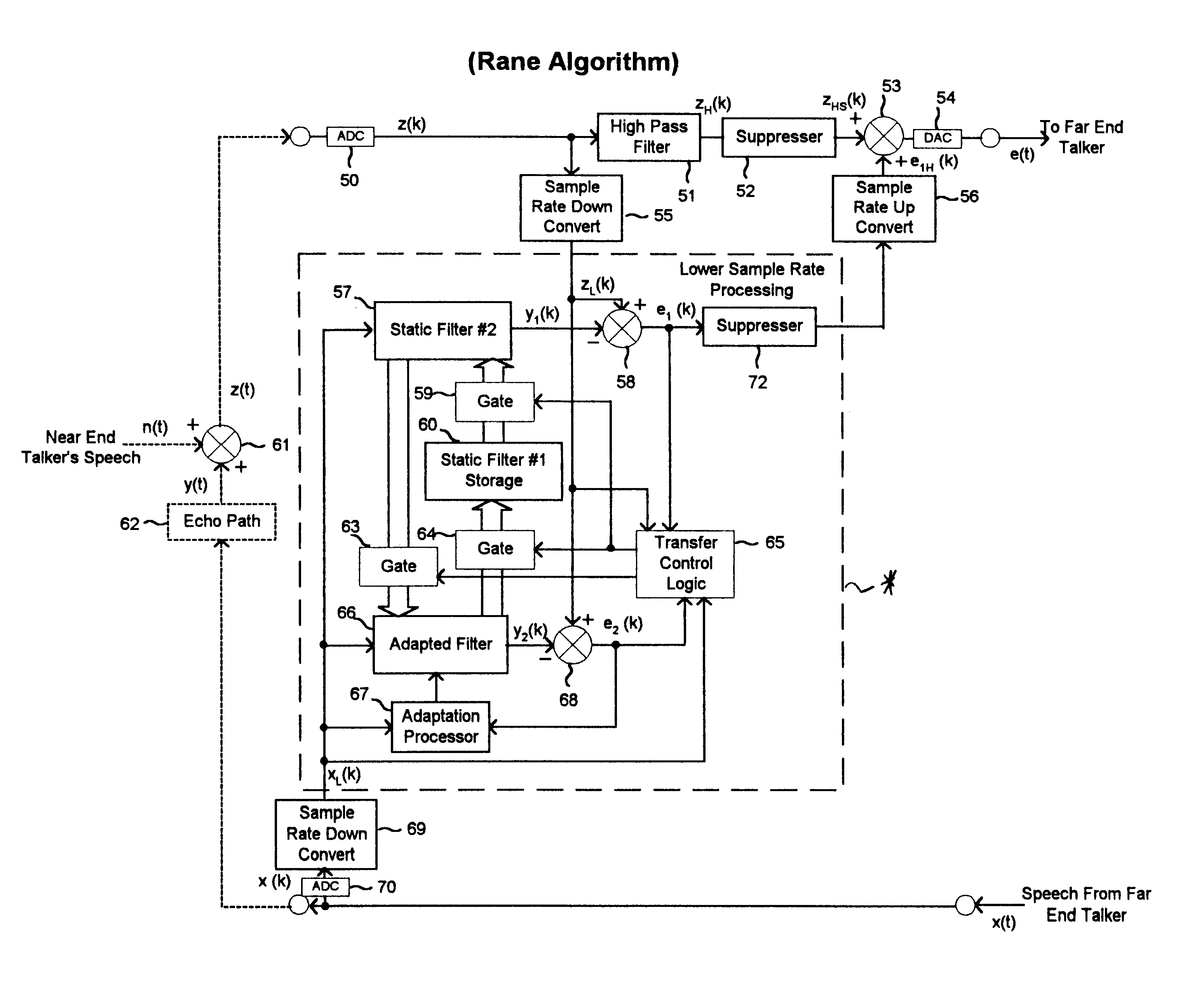
FIG. 6 shows the inventive algorithm based echo canceller. Continuous signals are shown as a function of time (t) in the figure. When a signal is converted to discrete time (becomes a digital signal) through the analog to digital conversion process it is shown as a function of (k). Physically this process is done using off the shelf analog to digital converters (ADC). Once in digital form the actual echo cancellation algorithm is performed on a Digital Signal Processing integrated circuit (another off the shelf device). The final step of the process is to convert the discrete time signal back to a continuous time version of the same using a digital to analog converter (DAC).

Description of Generic Commonly Used Signal Processing Blocks Found in FIGS. 5 and 6.

ADC and DAC (block numbers 1,3,12,50,54,70)

These are commonly performed functions (done with off the shelf hardware) that convert a continuous time signal to a discretely sampled one (ADC) or a discretely sampled signal to a cont...


PUM


Abstract

An echo cancellation invention which does away with the need for an accurate double-talk detector, while maintaining a higher adaptation gain for quicker convergence and also providing increased stability. It does this by operating two filter models of the acoustic path in parallel. One model is adapted continuously to find the most accurate model of the echo path, while the other is not. The echo canceller output is taken from the filter that is not adapted. A comparison of the residual error (echo) is done between the model being adapted and the model being listened to at regular intervals. When the model being adapted has less error (echo) than the model being listened to its filter coefficients are copied to the other model. If the model being adapted has greater error (echo) than the other model (caused by noise diverging the adaptation process) then the adapted model has its coefficients overwritten by the filter that is listened to. This process keeps error from accumulating in the adapted filter by removing divergence at regular intervals (improving overall convergence). Since the output is taken from the filter that is not adapted, higher adaptation gains may be used without fear of the user hearing any effects of adapting with a higher gain in the presence of noise.

Description

TECHNICAL FIELDThe invention is generally related to methods and apparatus for canceling echo in acoustic and electronic systems such as public address systems and teleconferencing systems. More specifically, there are two general categories of echo cancellation that the invention relates to: methods for controlling line echo cancellation and acoustic echo cancellation.BACKGROUND OF THE INVENTION“Acoustic echo” arises from the acoustic properties of a room as in a teleconferencing system. Acoustic echo originating at a near end location will be heard by a far end observer. Acoustic echo originating at a far end will be heard at the near end. An example with acoustic echo originating at the near end, while the far end transducers are acoustically isolated is shown in FIG. 1. From that figure it can be seen that acoustic echo will be heard at the far end of a conferencing system when the far end talker's voice gets acoustically coupled with the near end talker's microphone at the near...

Claims


Application Information

Patent Timeline
Patent Type & Authority Patents(United States)
IPC IPC(8): H04M1/00H04M9/08
CPCH04M9/082
Inventor TROXEL, DANA L.
Owner INMUSIC BRANDS
Why Eureka
Try Eureka