Hybrid rocket engine and method of propelling a rocket

a hybrid rocket engine and rocket technology, applied in the field of vortex flow, can solve the problems of limiting the design factor of the rate at which solid fuel grain can be caused to burn, the rate is typically slow, and the classical hybrid rocket engine, etc., to achieve the effect of facilitating and promoting high and uniform fuel grain regression rate, enhancing grain regression rate, and increasing combustion process efficiency

Inactive Publication Date: 2005-03-15
SIERRA NEVADA CORP
View PDF16 Cites 30 Cited by
  • Summary
  • Abstract
  • Description
  • Claims
  • Application Information

AI Technical Summary

Benefits of technology

A still further object of the present invention is to provide an improved hybrid rocket propulsion system that facilitates and promotes high and uniform fuel grain regression rates so that small combustion ports can be used in the propellant solid grain.
Another object of the present invention is to provide a hybrid propulsion system that inherently cools the case walls whenever fuel is not present to insulate the wall from

Problems solved by technology

In virtually all contemporary hybrids of today the limiting design factor is the rate at which the solid fuel grain can be caused to burn.
Because the rate is typically slow, conventional hybrid fuel grains must be made with large exposed surface areas.
Also, since fuel in a hybrid rocket engine is stored in the form of a solid grain, such engines require only half the feed system hardware of liquid bi-propellant engines.
However, despite these benefits, classical hybrid rocket engines, in which the oxidizer gas is injected into the combustion chamber at the end opposite the exit nozzle and in a direction parallel to the solid fuel grain, have not yet found widespread use for either commercial or military applications.
Reasons for this include the fact that they suffer fr

Method used


Image

  • Hybrid rocket engine and method of propelling a rocket
  • Hybrid rocket engine and method of propelling a rocket
  • Hybrid rocket engine and method of propelling a rocket

Examples


Embodiment Construction

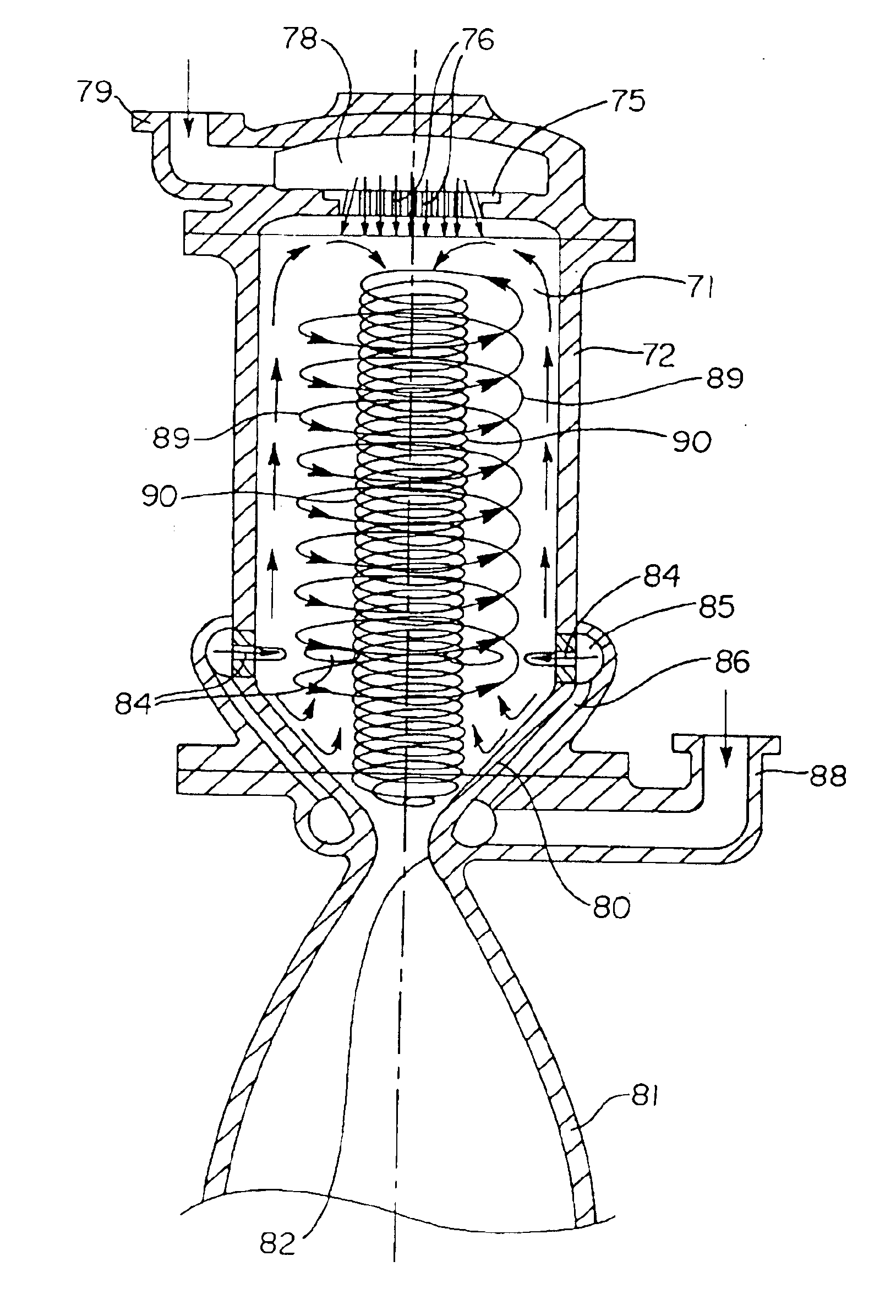
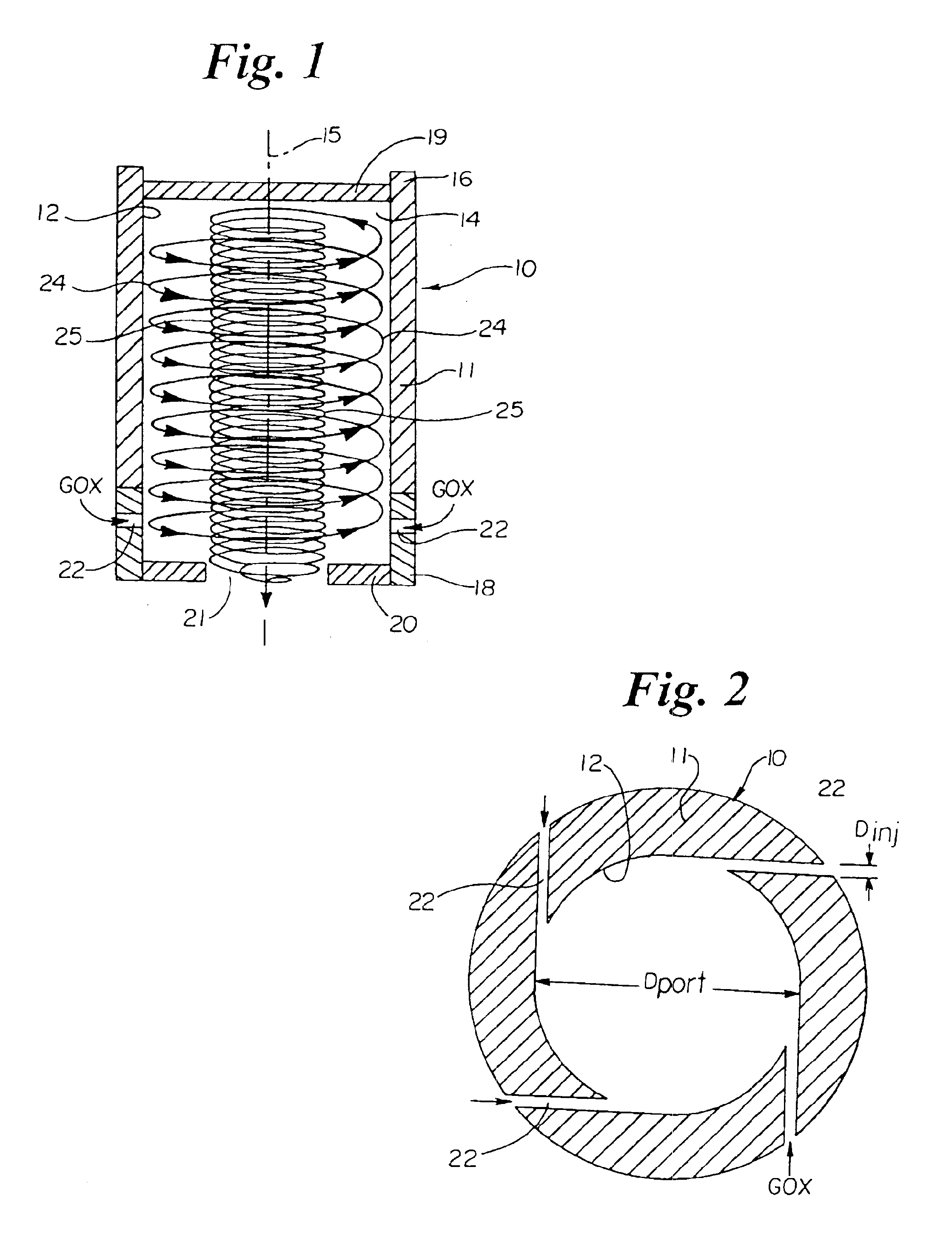
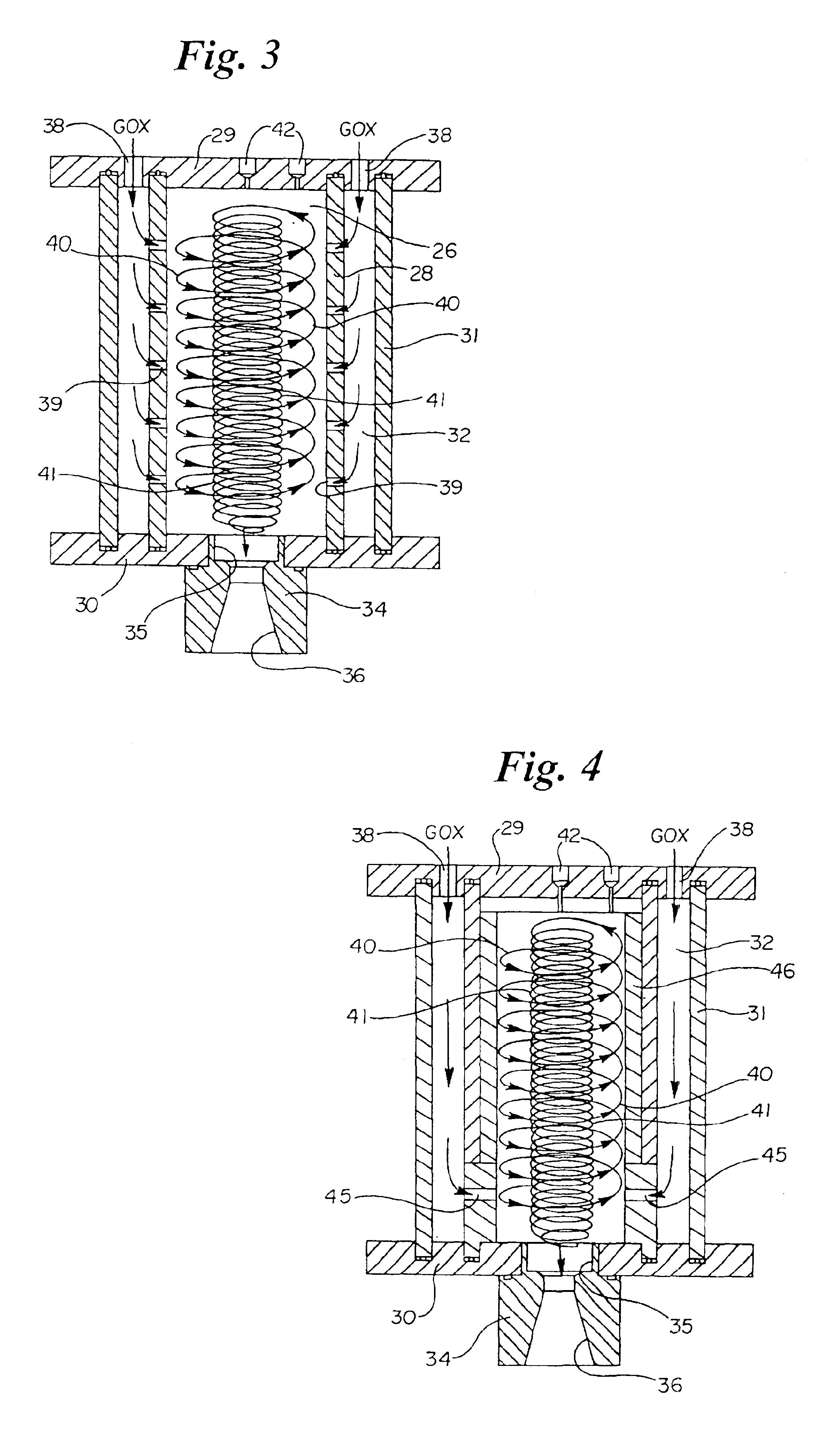
The flow field of the present invention is a double helical vortex flow field comprised of an outer vortex and a substantially concentric inner vortex which rotates in the same direction, but at a higher angular velocity. The inner and outer vortices are substantially discreet and advance in opposite axial directions. As described in greater detail below, the flow field of the present invention comprises a flow field axis having a first end and an opposite constricted second or exit end and three separate and discrete flow regions. These include a first flow region comprising a first or outer, substantially vortex fluid flow around the flow field axis and toward the first end, a second flow region comprising a substantially radial fluid flow from the first vortex fluid flow at the first end toward the flow field axis and a third flow region comprising a second or inner substantially vortex fluid flow around the flow field axis from the first end and toward the second end, with the s...


PUM


Abstract

A hybrid rocket engine and a method for propelling a rocket utilizing a vortex flow field. The flow field includes an outer fluid vortex spiraling toward a closed end of the flow field generating apparatus and an inner fluid vortex substantially concentric with the outer vortex spiraling away from the closed end and toward an outlet opening in which the inner vortex spirals in the same direction as the outer vortex, but in the opposite axial direction. The invention also relates to a rocket propulsion system utilizing the flow field in which the propulsion system includes a combustion chamber with a fuel source and an oxidizer source that deliver the said fuel and said oxidizer to the said outer and inner vortexes in a manner to support a combustion process while flowing along the flow field.

Description

BACKGROUND OF THE INVENTION1. Field of the ArtThe present invention relates generally to a vortex flow field and the apparatus and method to produce and sustain it and more particularly to a hybrid rocket engine and a method of propelling a rocket utilizing such vortex flow field. The flow field in accordance with the present invention is capable of providing separate regions or zones within and among one or more flowing fluids contained within a common chamber, without the need for diaphragms or other physical separators or barriers. It is evident and believed that the flow field of the present invention has utility to a wide range of applications. One general field of application is that of combustion chambers, and more particularly, that of combustion chambers and methods for rocket engines or the like and hybrid rocket propulsion systems. A combustion chamber and method in accordance with one embodiment of the present invention utilizes the unique flow field of the present inven...

Claims


Application Information

Patent Timeline
IPC IPC(8): F02K9/52F02K9/64F02K9/00F02K9/62F23R3/58F23R3/00F23C3/00
CPCF02K9/52F02K9/62F23R3/58F23C3/006F02K9/64
Inventor KNUTH, WILLIAM H.CHIAVERINI, MARTIN J.GRAMER, DANIEL J.
Owner SIERRA NEVADA CORP
Why Eureka
Try Eureka