Electromagnetically driven valve control apparatus and electromagnetically driven valve control method for internal combustion engine

a technology of electromagnetically driven valves and control apparatuses, which is applied in electrical control, non-mechanical valves, instruments, etc., can solve the problems of not being able to perform different control methods for electromagnetically driven valves in a satisfactorily meticulous manner, and the electromagnetically driven method has not been widely used, so as to reduce operation noise, increase the number of processing units, and control

Inactive Publication Date: 2005-03-15
TOYOTA JIDOSHA KK
View PDF15 Cites 61 Cited by
  • Summary
  • Abstract
  • Description
  • Claims
  • Application Information

AI Technical Summary

Benefits of technology

It is an object of the invention to appropriately distribute processing power of processing units such as the CPUs, which control electromagnetically driven valves. It is another object of the invention to provide a techno...

Problems solved by technology

However, the electromagnetically driving method has not been widely used, and various techniques are proposed for putting the electromagnetically driving method to practical use.
However, for example, an on-vehicle CPU which is easily available, and whose operating frequency is approximately several tens of megahertz to several h...

Method used


Image

  • Electromagnetically driven valve control apparatus and electromagnetically driven valve control method for internal combustion engine
  • Electromagnetically driven valve control apparatus and electromagnetically driven valve control method for internal combustion engine
  • Electromagnetically driven valve control apparatus and electromagnetically driven valve control method for internal combustion engine

Examples


first embodiment

(First Embodiment)

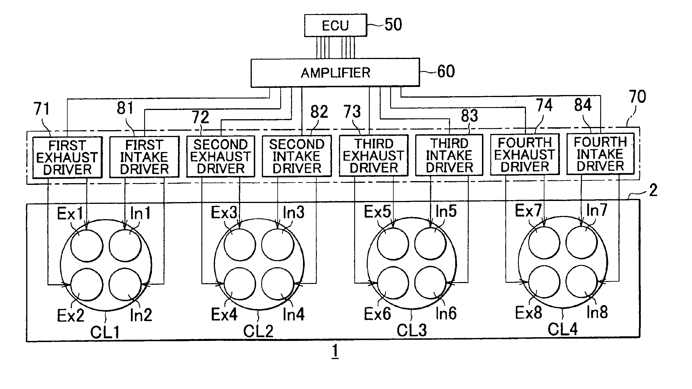
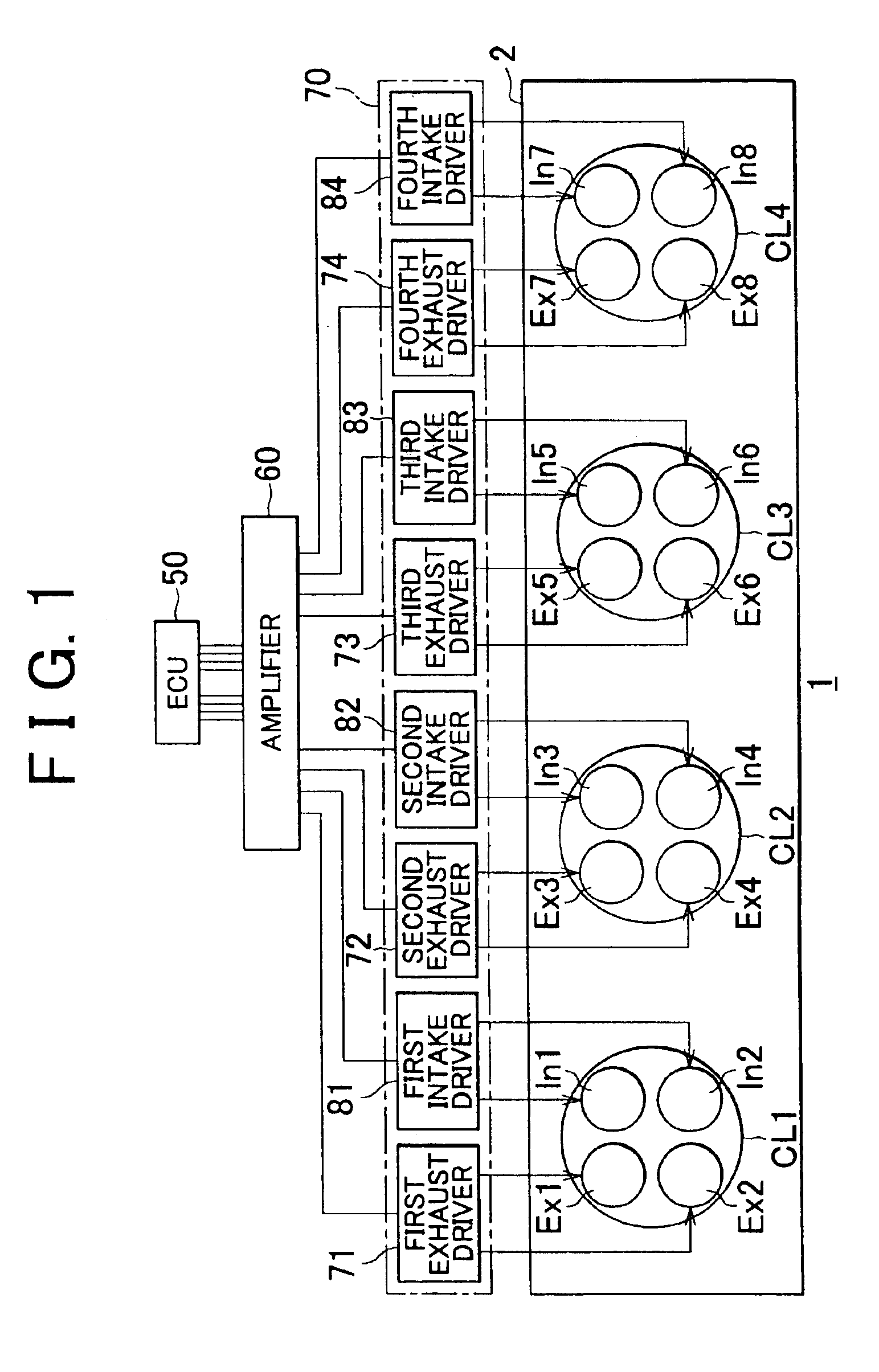
FIG. 1 is a schematic diagram showing a configuration of an in-line four-cylinder internal combustion engine according to the first embodiment of the invention. The internal combustion engine 1 includes an engine body 2 including a first cylinder CL1 to a fourth cylinder CL4. Each of exhaust valves and intake valves is composed of an electromagnetically driven valve 200, which will be described with reference to FIG. 2. The operation of each of the electromagnetically driven valves is controlled by an ECU 50, an amplifier 60, and a valve driver 70. The ECU 50 is an electromagnetically driven valve control device. The amplifier 60 has a D / A conversion function and an amplification function. The valve driver 70 includes a first exhaust valve driver 71 to a fourth exhaust valve driver 74 and a first intake valve driver 81 to a fourth intake valve driver 84. The first exhaust valve driver 71 to the fourth exhaust valve driver 74 control an exhaust valve Ex1 to an exhau...

second embodiment

(Second Embodiment)

In the embodiment, the invention is applied to an in-line six-cylinder internal combustion engine 1. The configuration and the operation of the electromagnetically driven valve 200 is the same as in the first embodiment. FIG. 12 shows a configuration of the in-line six-cylinder internal combustion engine 1 which includes the first cylinder CL1 to the sixth cylinder CL6 according to the invention. Unlike the configuration shown in FIG. 1, an engine body 2 includes a fifth cylinder CL5 and a sixth cylinder CL6. In the fifth cylinder CL5, a ninth exhaust valve Ex9 and a tenth exhaust valve Ex10, and a ninth intake valve In9 and a tenth intake valve In10 are provided. In the sixth cylinder CL6, an eleventh exhaust valve Ex11 and a twelfth exhaust valve Ex12, and an eleventh intake valve In11 and a twelfth intake valve In12 are provided. The valve driver 70 includes a fifth exhaust driver 75, a fifth intake driver 85, a sixth exhaust driver 76, and a sixth intake drive...

third embodiment

(Third Embodiment)

In the third embodiment, the invention is applied to a V-8 internal combustion engine 1. FIG. 16 shows a configuration of the internal combustion engine 1 according to the embodiment. The internal combustion engine 1 is different from the internal combustion engine 1 in the second embodiment in that a seventh cylinder CL7 and an eighth cylinder CL8 are provided, and correspondingly, the valve driver 70 includes a seventh exhaust driver 77 and a seventh intake driver 87, and an eighth exhaust driver 78 and an eighth intake driver 88.

FIG. 17 is a block diagram schematically showing a configuration of the ECU 50 which controls the electromagnetically driven valves 200 according to the embodiment. The first sub CPU 51a controls the first intake valve In1 and the second intake valve In2 in the first cylinder CL1, and the eleventh intake valve In11 and the twelfth intake valve In12 in the sixth cylinder CL6. The second sub CPU 51b controls the third intake valve In3 and ...


PUM


Abstract

A main CPU determines whether or not there is a request for one valve driving based on an engine operating state such as an engine speed and a load factor, with reference to a control map. When it is determined that there is a request for one valve driving, it is determined whether or not there is an overlapping period between opening periods. When it is determined that there is no overlapping period, a high speed control is performed for controlling electromagnetically driven valves. When it is determined that there is no request for one valve driving, or when it is determined that there is the overlapping period, a low speed control is performed for controlling electromagnetically driven valves.

Description

INCORPORATION BY REFERENCEThe disclosure of Japanese Patent Application No. 2002-346229 filed on Nov. 28, 2002, including the specification, drawings and abstract is incorporated herein by reference in its entirety.BACKGROUND OF THE INVENTION1. Field of the InventionThe invention relates to a technique for performing a driving control of an engine valve of an internal combustion engine using electromagnetic force.2. Description of the Related ArtAs a method for driving an intake valve and an exhaust valve which are engine valves of an internal combustion engine, an electromagnetically driving method in which the engine valves are driven using electromagnetic force is known. According to the electromagnetically driving method, opening / closing timing of the intake valve and the exhaust valve can be easily optimized in accordance with an operating state of the internal combustion engine (hereinafter, referred to simply as “engine operating state”), and combustion efficiency of the inte...

Claims


Application Information

Patent Timeline
IPC IPC(8): F01L1/26F02D41/20F02D13/02F01L9/04F02F1/42F02D41/00F02D41/26F01L9/20
CPCF01L1/267F01L9/04F02D41/20F02F1/4214F02D13/0253F01L2009/0436F01L2800/00Y02T10/18F02D41/266F02D2041/001Y02T10/12F01L2009/2136F01L9/20
Inventor HAYASE, YUICHIROTSUBONE, KENJIYANAI, AKIHIROKADOWAKI, YOSHINORIFUWA, TOSHIO
Owner TOYOTA JIDOSHA KK
Why Eureka
Try Eureka