Injection molding machine having a screw support base moved by an actuator

a technology of injection molding machine and actuator, which is applied in the direction of auxillary shaping apparatus, manufacturing tools, food shaping, etc., can solve the problems of poor efficiency of the screw shaft for converting the rearward movement into the rotating motion, inability to improve control responsiveness, and inability to accurately control the rotation of the screw. , the effect of improving the quietness

Inactive Publication Date: 2005-03-15
MEIKI
View PDF6 Cites 8 Cited by
  • Summary
  • Abstract
  • Description
  • Claims
  • Application Information

AI Technical Summary

Benefits of technology

In the invention, since the actuator of the screw movement means does not interfere with the screw rotating motor to which the rear end of the screw is connected by disposing the actuator on the heating cylinder side, a relatively large screw rotating motor can be employed, thereby the screw rotating motor can be made compact in its axial direction.
Further, the rear end of the screw is spline-connected inside of the rotating output section of the screw rotating motor, thereby the screw rotating motor can be made more compact in its axial direction. Furthermore, since the screw can be directly driven in rotation without using a gear and a belt, the rotation of the screw can be accurately controlled as well as the quietness thereof is improved.

Problems solved by technology

Accordingly, a problem arises in that a small force such as the back pressure caused by the rearward movement of the screw in the metering cannot be effectively converted, the back pressure to be controlled is dispersed, and thus the back pressure in the metering cannot be accurately controlled.
This is because the efficiency of the screw shaft for converting the rearward movement into the rotating motion is bad.
Further, in this technology, a problem arises in that the control responsiveness cannot be improved and the back pressure cannot be accurately controlled in the metering.
This is because the position of the screw in the metering cannot help being controlled, so to speak, only indirectly by controlling the rotating force converted from the rearward movement of the screw simply by a brake.
Further, in the technology, in which the load cell is mounted on the member receiving the load applied by the rearward movement of the screw to detect the molding material pressure produced to the screw, of the conventional technologies described above, when the electric signal, from which the electric disturbance such as noise, and the like has been eliminated by the given constant, is captured as the feedback signal in the injection and metering, a problem arises in that the electric signal cannot be used as an effective control signal for controlling the axial movement of the screw in the injection and metering.
This is because the magnitude, control responsiveness, and frequency band of the output electric signal are not proper in the injection and the metering.
Further, in this technology, the linearity between the received back pressure and the output signal of the load cell is bad and thus it is difficult to accurately control the back pressure of the screw.
Furthermore, in the technology in which the permanent magnet is used to drive the servo motor for controlling the axial movement of the screw, a problem arises in that the axial movement of the screw cannot be accurately controlled.
This is because a cogging torque produced by the permanent magnet of the servo motor makes the torque of the screw shaft unstable and a pulsation is produced thereby.
The influence caused by the above problems becomes serious particularly when the relatively small back pressure in the metering and the holding pressure after injection and filling of the molding material pressure are controlled.
In addition to the above problems, a problem is also arisen in that the dimension of the injection device is increased in the axial direction and a relatively large installation space is necessary, thereby the injection device cannot be made compact.
Then, there is a possibility that a problem is arisen in quietness in operation due to friction noise and gear mesh noise.
Further, a problem is arisen in that it is difficult to improve controllability because there is a possibility that an error is caused in the rotation control of the screw by an increase in backlash, and the like due to wear.

Method used


Image

  • Injection molding machine having a screw support base moved by an actuator
  • Injection molding machine having a screw support base moved by an actuator
  • Injection molding machine having a screw support base moved by an actuator

Examples


Embodiment Construction

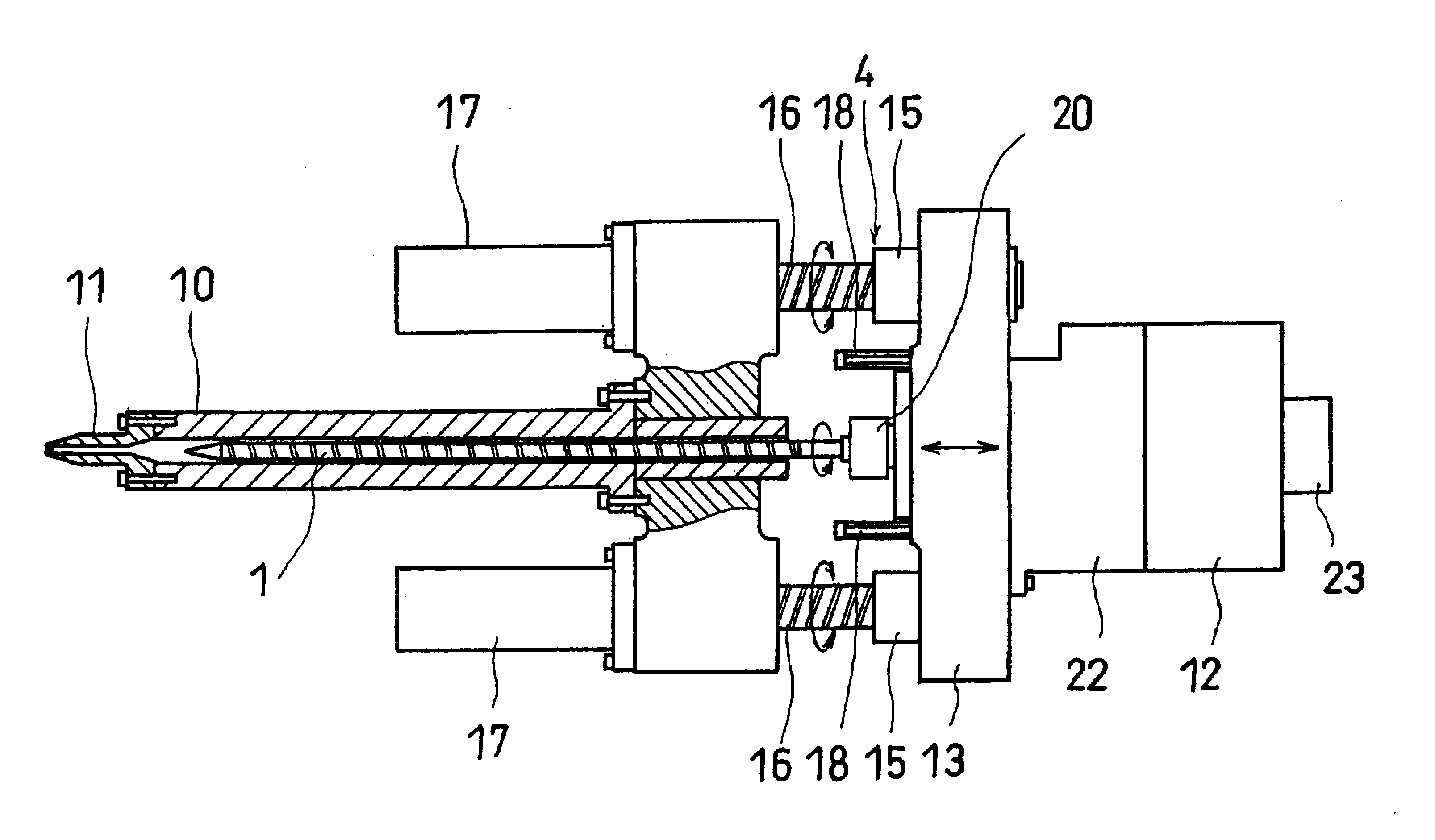
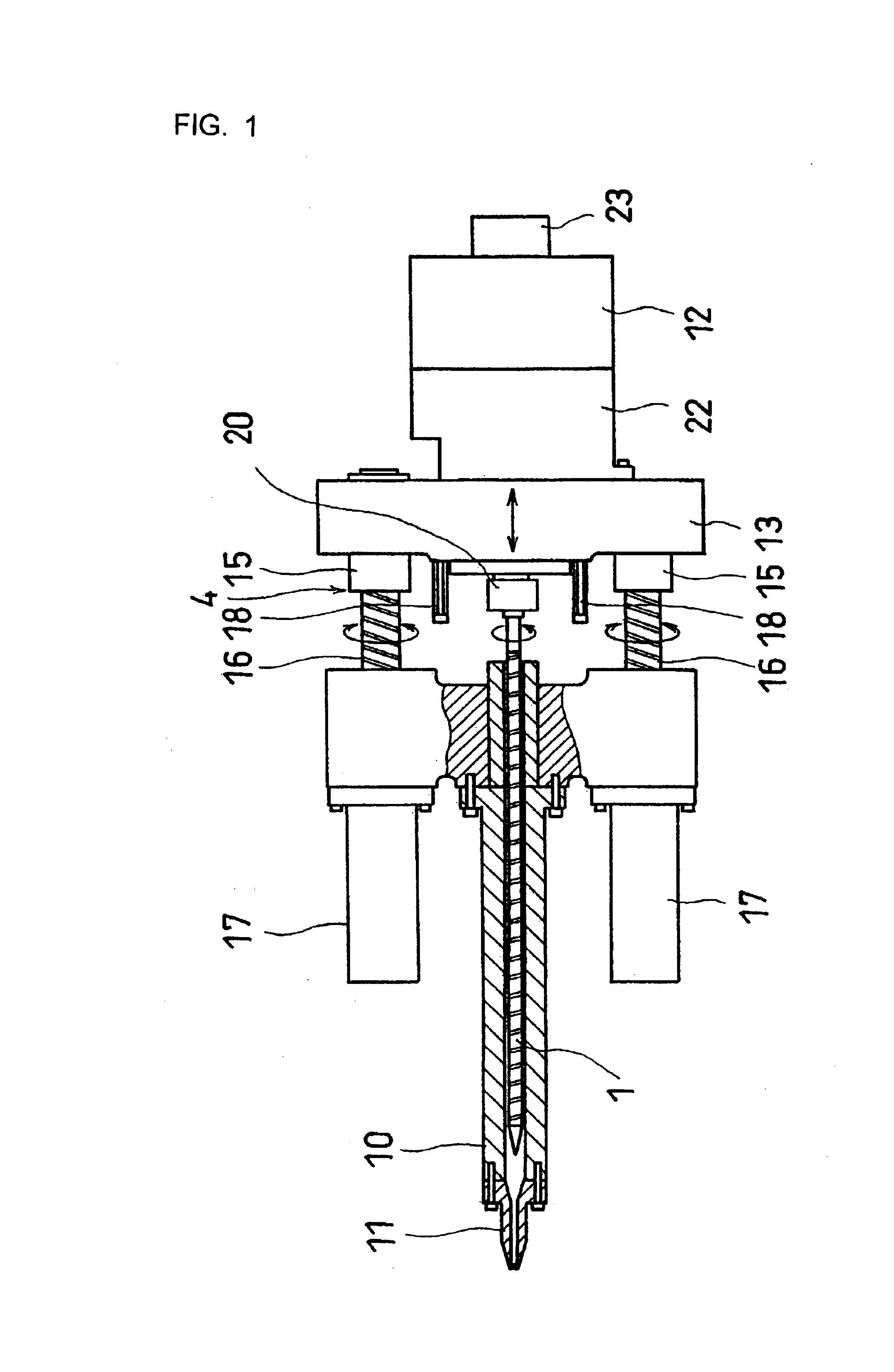
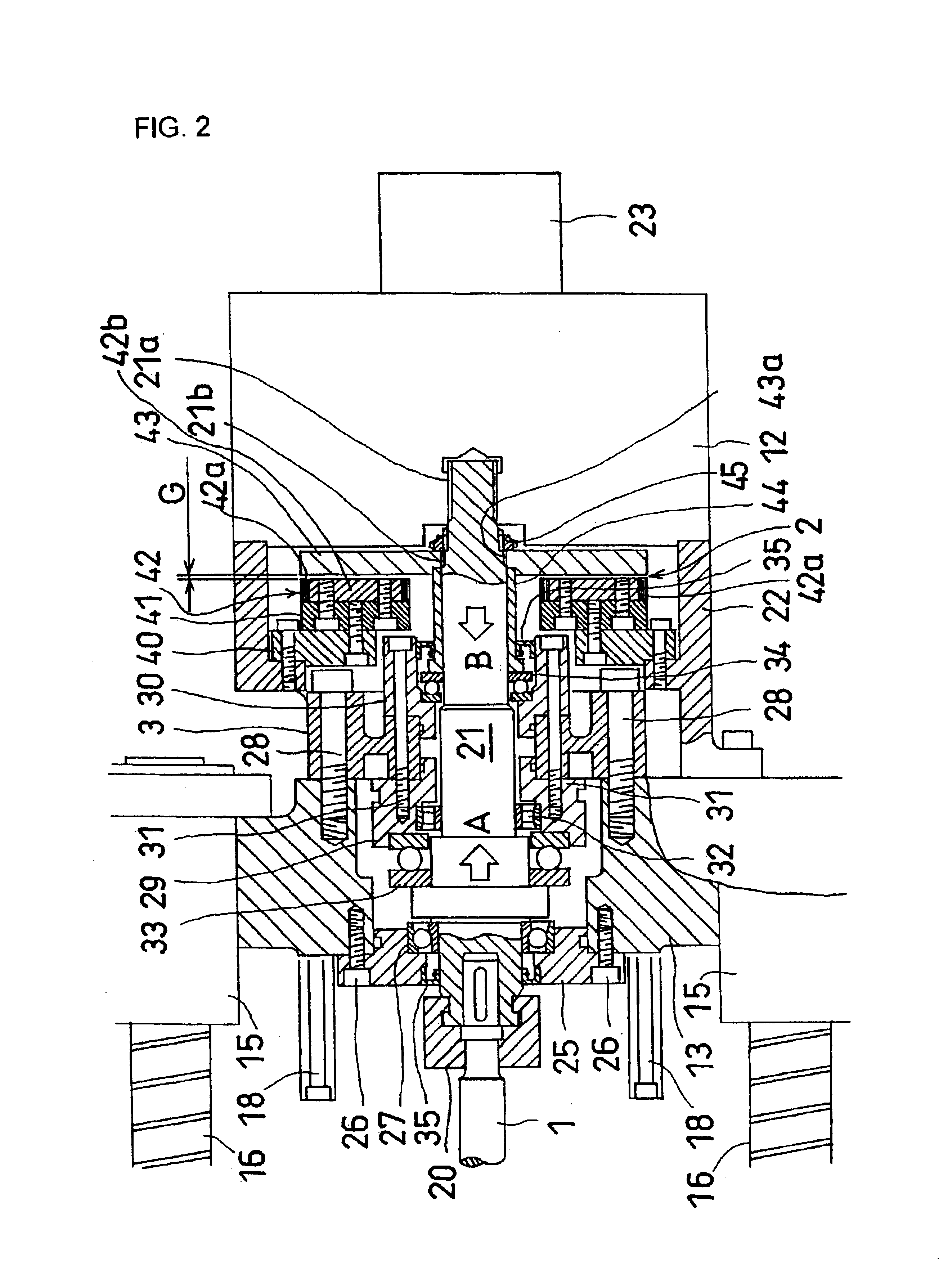
First, an embodiment of an injection molding machine of the present invention will be described in detail based on FIGS. 1 to 7. Note that FIGS. 2 and 4 show different embodiments of the injection molding machine of the present invention in enlargement. In the following description, the same reference numerals denote the same or corresponding portions.

The injection molding machine of the present invention generally includes a pre-pressure addition means 2 for adding a pre-pressure (an arrow B in FIG. 2) acting in the opposite direction of a molding material pressure (an arrow A in FIG. 2) received by a screw 1 to a detection means 3 for detecting the axial pressure of the screw 1 and / or to the screw 1, the detection means 3 for detecting the axial pressure of the screw 1 (arrows A and B of FIG. 2), and a screw axial pressure control means 4 for controlling the axial pressure based on a difference between the pre-pressure B and the molding material pressure A, wherein the pre-pressur...


PUM

PropertyMeasurementUnit
movementaaaaaaaaaa
pressureaaaaaaaaaa
period of timeaaaaaaaaaa

Abstract

An injection molding machine comprises a pre-pressure addition means 2 adding a pre-pressure B acting in the opposite direction of a molding material pressure A received by a screw 1 to a detection means 3 and/or the screw 1, the detection means 3 detecting the axial pressures A and B of the screw, and a screw movement control means 4 controlling the axial pressure based on a different between the pre-pressure B and the molding material pressure A, wherein the pre-pressure addition means 2 is made non-contact with the direction means 3, a forward and backward driving motor 17 is disposed adjacent to a heating cylinder 10, and a screw connector 21 at the rear end of the screw 1 is spline-connected inside a rotating rotor of a screw rotating motor 12. According to the machine, the molding material pressure received by the screw can be accurately detected without being affected by the wear of the machine so as to properly control the axial pressure of the screw and to make the machine compact.

Description

TECHNICAL FIELDThe present invention relates to an injection molding machine and a method of controlling the injection molding machine, and more particularly to an injection molding machine and a method of controlling the injection molding machine having a screw inserted into a heating cylinder so as to be rotated about an axis and moved along an axial direction.BACKGROUND ARTGenerally, in an injection device of an injection molding machine, a screw rotating motor is connected to the rear end of a screw inserted into a heating cylinder to rotate the screw about an axis in the heating cylinder, as shown in FIG. 1. Then, the screw rotating motor is disposed such that the rotary shaft of the rotating rotor thereof projects forward (not shown) and connected to the screw through a coupling, and the like. Further, the injection device includes a screw moving means (refer to reference numeral 4 of FIG. 1) to movably support the screw axially rearward and forward. A servo motor using a perm...

Claims


Application Information

Patent Timeline
Patent Type & Authority Patents(United States)
IPC IPC(8): B29C45/76B29C45/50B29C45/46
CPCB29C45/5008B29C45/76B29C2045/1792B29C2045/5032B29C2945/76006B29C2945/76187B29C2945/76859B29C2945/76498B29C2945/76511B29C2945/76525B29C2945/76568B29C2945/76665B29C2945/76307B29C45/50
Inventor MORITA, RYOZOTOMITA, SATOSHIMIYAKI, TSUYOSHIOKA, KEIJIROSEKIYAMA, TOKUZOUSHIBUYA, HIROSHINISHIDA, SATOSHI
Owner MEIKI
Why Eureka
Try Eureka