Laboratory centrifuge, comprising refrigeration unit

a technology of centrifuge and refrigeration unit, which is applied in the direction of centrifuges, refrigeration machines, refrigeration safety arrangements, etc., can solve the problems of increasing construction costs, increasing rotational speed and cooling power, and reducing construction costs, so as to simplify construction, improve cooling control, and simplify the effect of motor control

Inactive Publication Date: 2005-03-15
EPPENDORF AG
View PDF21 Cites 27 Cited by
  • Summary
  • Abstract
  • Description
  • Claims
  • Application Information

AI Technical Summary

Benefits of technology

According to the invention, not only the centrifuge motor but also the cooling motor have their rotational speeds controlled by controlling the frequency. This results in a possibility of better cooling control and permits to significantly simplified the construction. To this end, the already available frequency converter should be supplemented with a further inverted rectifier. Additional switching and control devices for the cooling motor are not necessary. A significant constructional simplification of the motor control is obtained which results in the costs reduction. In laboratory centrifuges, this is of a particular importance, as these can be successfully marketed essentially only as table apparatuses as small and economical as possible.
The control unit, which controls the frequency converter, can control both inverted rectifiers with the same frequency. The drawback of this consists in that both the rotational speed and the cooling power are increased and decreased together. Therefore, advantageously, the control unit controls the two inverted rectifiers independently from each other. These features make it possible to separately control, as needed, the rotational speed and the cooling power.
With centrifuges, it is necessary to bring the rotor to a stop as soon as possible after a centrifuge process ends in order to be able to remove centrifuged samples in short time. When the control frequency for the centrifuge inverter rectifier decreases, it supplies a high braking current in a d.c. source so that its voltage can reach an impermissible high value. According to the state of the art, the returned brake power is consumed, if required, in connectable brake resistances which increases the construction costs. Therefore, advantageously, control unit controls the two inverted rectifiers with a predetermined reduction of frequency if the frequency of the centrifuge inverted rectifier is reduced. In this way, during braking of the centrifuge motor, the returned brake power, at least partially is converted into current consumed from the d.c. source by the cooling motor that functions as a brake resistance. Therefore, the number of additional brake resistances can be substantially reduced or be completely eliminated, whereby the costs of a centrifuge is further reduced. A complete separate control of the driving powers of the centrifuge motor and the cooling motor can lead to a simultaneous full load in each of the two motors, and both the d.c. source and the mains power rectifier must be designed for this case. Therefore, advantageously, the control unit reduces the frequency of the cooling inverted rectifier during acceleration of the centrifuge motor. Such control connection of both motors ensures that both accelerations of the rotor when the centrifuge motor requires a lot of power, the cooling motor is driven with less power. As a result, the maximal power to-be-fed from the d.c. source is reduced, so the components can be reduced, which again can reduce the cost of the centrifuge.
Advantageously, the control unit turns off the cooling inverted rectifier below a minimal frequency. In this way it is insured that the cooling motor runs at a speed below the minimal rotational speed only for a short time. This is an advantage when conventional cooling units with a compressor are used for lubrication reasons, should operate above a minimal rotational speed.

Problems solved by technology

The drawback of this consists in that both the rotational speed and the cooling power are increased and decreased together.
According to the state of the art, the returned brake power is consumed, if required, in connectable brake resistances which increases the construction costs.

Method used


Image

  • Laboratory centrifuge, comprising refrigeration unit
  • Laboratory centrifuge, comprising refrigeration unit

Examples


Embodiment Construction

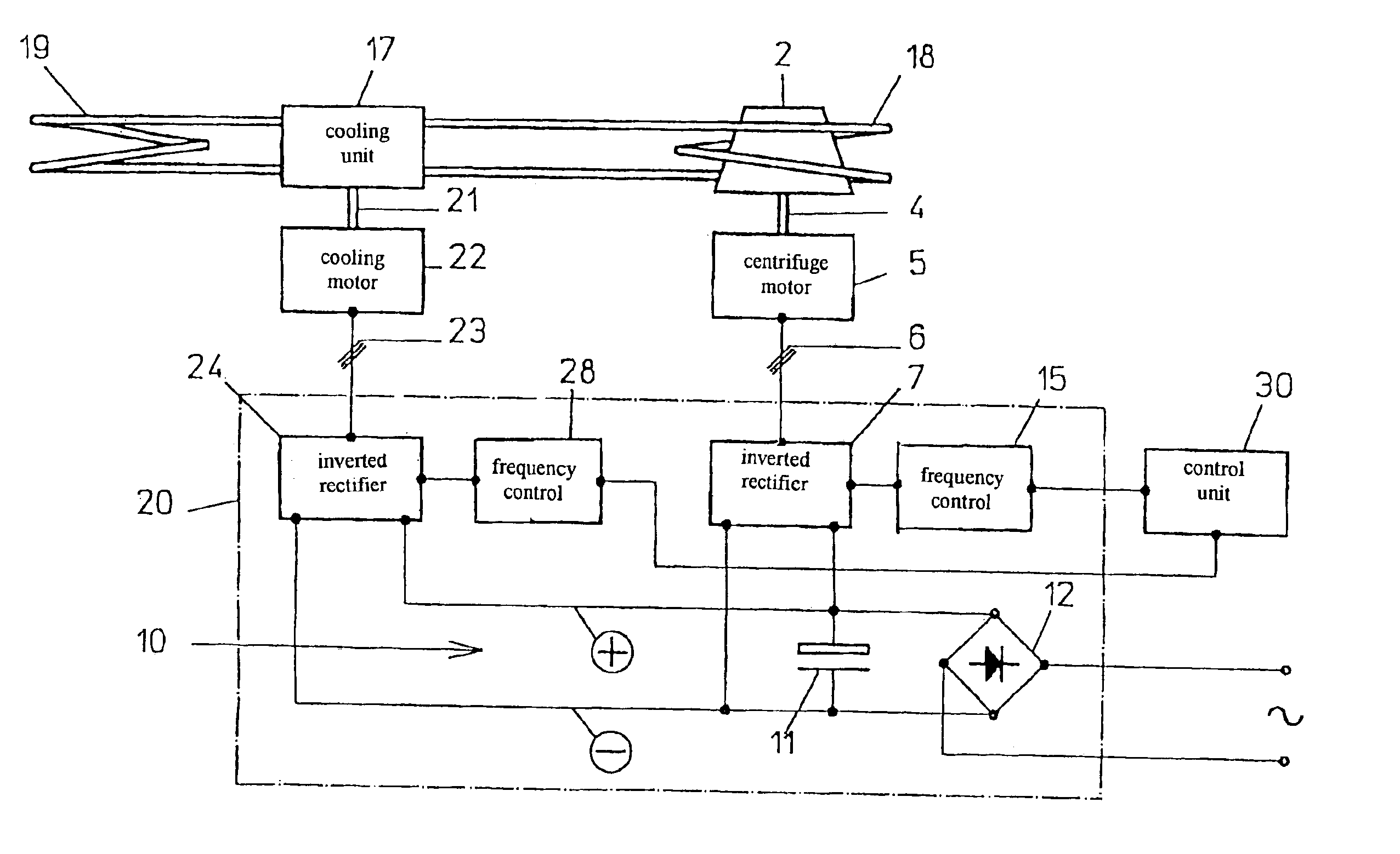
The centrifuge has a rotor 2 that has inwardly located seats (not shown) for a conventional centrifuge vessel. The rotor 2 is driven by a centrifuge motor 5 via a shaft 4. The motor 5 is formed as a three-phase induction motor.

The centrifuge motor 5 is fed from a centrifuge inverted rectifier 7 of a frequency converter 20 via three conductors 6. In the frequency converter 20, the centrifuge inverted rectifier 7 has its input conductors connected with plus and minus wires of a d.c. source 10.

The d.c. source 10 has, between the plus and minus wires, a conventional charging capacitor 11 and is fed from a mains power rectifier 12 that is connected by appropriate conductors with a.c. mains.

The centrifuge inverted rectifier 7 is connected to a frequency control 15 by control conductors. The frequency control feeds the frequency and voltage to the centrifuge inverter rectifier 7, with which the centrifuge motor 5 is controlled.

There is provided a cooling unit 17, in a very simplified repre...


PUM


Abstract

A laboratory with a rotor driven by a centrifuge electric motor and a cooling unit driven by an electrical cooling motor, wherein the centrifuge motor is formed as a frequency-controlled induction motor fed from a frequency converter controlled by a control unit and having a centrifuge inverted rectifier that feeds the centrifuge motor and is connected to a d.c. source fed from a mains power rectifier, characterized in that the cooling motor is formed as a frequency-controlled induction motor, and that the frequency converter has a further cooling inverted rectifier connected to the d.c. source parallel to the centrifuge inverted rectifier for feeding the cooling motor.

Description

BACKGROUND OF THE INVENTION1. Field of the InventionThe present invention relates to a laboratory centrifuge with an electric centrifuge motor.2. Description of the Prior ArtIn laboratory centrifuge of this type, it is common, as described in DE-41 36 514 C2, to form the centrifuge motor as a frequency-controlled induction motor that is fed by a frequency converter. This permits to achieve a required precision of adjustment of the motor rotational speed necessary for the centrifuge operation.Also known are laboratory centrifuges having a cooling unit driven by an electric motor. In those, in accordance with the existing state of the art, the cooling motors have a simple design with a constant rotational speed, with the cooling power being controlled by switching the motor on and off.DE-35 23 818 C3 discloses an air-conditioner the motor operation of which is frequency controlled.The object of the present invention is to provide a laboratory centrifuge having a centrifuge motor with ...

Claims


Application Information

Patent Timeline
Patent Type & Authority Patents(United States)
IPC IPC(8): B04B15/00B04B15/02B04B9/10B04B9/00F25B1/00F25B49/00
CPCB04B15/02B04B9/10
Inventor MULLER, HEIKOKACHE, HORST
Owner EPPENDORF AG
Why Eureka
Try Eureka