
Dispensing system and method

a technology of dispensing system and dispensing method, which is applied in the direction of container/bottle construction, rigid containers, special dispensing means, etc., can solve the problems of increasing the number of encoders, and reducing the gear ratio of the motor

Inactive Publication Date: 2005-03-15
KPS SPECIAL SITUATIONS FUND II LP
View PDF9 Cites 63 Cited by
  • Summary
  • Abstract
  • Description
  • Claims
  • Application Information

AI Technical Summary

Benefits of technology

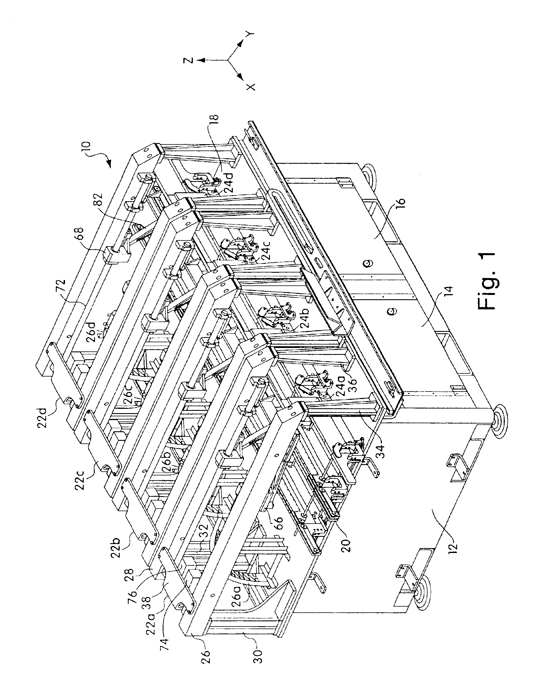
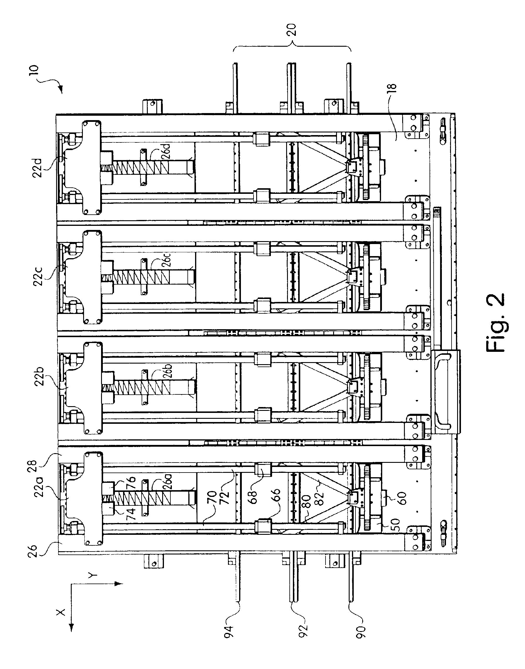
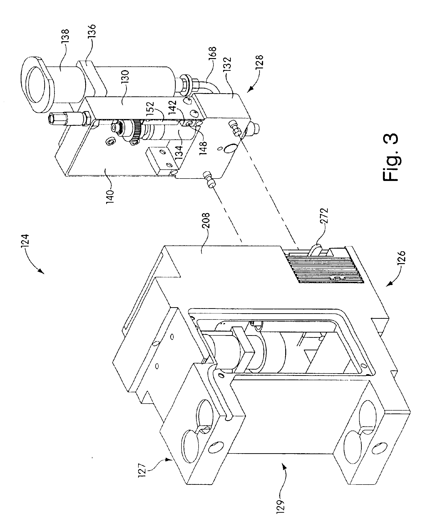
[0018]In another general aspect, the invention features a dispensing system for dispensing material onto a substrate. The dispensing system includes a frame, a support, coupled to the frame, that supports the substrate at a dispensing position in the dispensing system, and a dispensing head, coupled to the frame, that dispenses the material onto the substrate. The dispensing head includes a motor unit having a motor coupled to an output drive mechanism, a dispensing unit having a material outlet from which the material is dispensed, the dispensing unit having a dispensing mechanism coupled to the material outlet, and means for removably coupling the motor unit to the dispensing unit such that operation of the motor causes the dispensing mechanism to dispense material through the outlet.
[0025]The material can be one of silver epoxy, surface mount adhesive, flux and solder paste. The apparatus can further include a motor with an encoder, an auger screw that is rotated by the motor to cause material to be dispensed, and means for reducing a gear ratio of the motor to increase a number of encoder counts per degree of revolution of the auger screw. The apparatus can further include means for lowering the dispenser towards the electronic substrate, means for maintaining the motor at a fixed position while the dispenser is lowered, means for measuring a height of the electronic substrate.

Problems solved by technology

These dispensing systems typically are only able to dispense one material at a time, and the throughput of product in these systems may be less than desired because of the time required to dispense multiple materials serially using one dispensing head.
This solution is expensive since two complete machines are used, and since additional manufacturing space is required.
Printed circuit boards continue to become more densely populated, and circuit components continue to become smaller.
Therefore, the acceleration and deceleration of these pumps is not well controlled, making it difficult to accurately control dispensing.
Therefore, these pumps are typically not used to dispense small dots having diameters less than 0.010 inches.
However, for dispensing of solder pastes, silver epoxies and other adhesives in the electronics industry, when a needle with an inner diameter of less than approximately 5 mils is used, clogging of the needle often occurs due to the size of particles contained in these materials.
The clogging of the needle causes unrepeatable dispensing results.

Method used


Image

  • Dispensing system and method
  • Dispensing system and method
  • Dispensing system and method

Examples


first embodiment

[0031]FIG. 5 is a first exploded view of a dispensing unit used in the dispensing head of FIG. 3;

[0032]FIG. 5A is a cross-sectional view of an alignment pin used in embodiments of the present invention;

[0033]FIG. 6 is a second exploded view of the dispensing unit shown in FIG. 5;

[0034]FIG. 7 is an exploded view of a motor unit used in the dispensing head of FIG. 3;

[0035]FIG. 8 is an exploded view of a front plate assembly used in the motor unit of FIG. 7;

second embodiment

[0036]FIG. 9 is a first exploded view of a dispensing unit used in the dispensing head of FIG. 3;

[0037]FIG. 10 is a second exploded view of the dispensing unit of FIG. 9;

[0038]FIG. 11 is a second embodiment of a dispensing system of the present invention;

[0039]FIG. 12 is a perspective view of another embodiment of a dispensing unit used with dispensing systems of the present invention; and

[0040]FIG. 13 is an exploded view of a cartridge sleeve used in the dispensing unit of FIG. 12.


PUM

PropertyMeasurementUnit
diameteraaaaaaaaaa
diametersaaaaaaaaaa
diameteraaaaaaaaaa

Abstract

A dispensing system and method for dispensing material onto a substrate. The dispensing system includes a frame, a support, coupled to the frame, that supports the substrate at a dispensing position in the dispensing system, and a dispensing head, coupled to the frame, that dispenses the material onto the substrate. The dispensing head includes a motor unit having a first motor coupled to an output drive mechanism, and a dispensing unit, removably coupled to the motor unit, having a material outlet from which the dispensing material is dispensed, the dispensing unit having a dispensing mechanism coupled to the material outlet and coupled to the output drive mechanism of the motor unit such that operation of the first motor causes the dispensing mechanism to dispense material through the outlet. The dispensing head may be controlled for deposition of dots of material having diameters smaller than a dispensing needle of the dispensing unit.

Description

RELATED APPLICATIONS[0002]This application is a continuation-in-part of U.S. patent application Ser. No. 10 / 156,715, filed May 28 2002, now abandoned, which is a continuation of U.S. patent application Ser. No. 09 / 643,324, filed Aug. 22, 2000, now U.S. Pat. No. 6,395,334, which is a divisional application of U.S. Ser. No. 09,253,119, filed Feb. 19, 1999, now U.S. Pat. No. 6,214,117, each of which is incorporated herein by reference.FIELD OF THE INVENTION[0003]The present invention relates generally to an apparatus and method for performing a plurality of work operations in parallel using a plurality of work devices within one workstation. More specifically, the present invention relates to an apparatus and method for dispensing material onto a substrate using one or more dispensing heads in a dispensing system. In addition, specific embodiments are directed to dispensing systems for dispensing microdots of material.BACKGROUND OF THE INVENTION[0004]There are several types of prior ar...

Claims


Application Information

Patent Timeline
Patent Type & Authority Patents(United States)
IPC IPC(8): B23K3/06B05D1/26B05C5/00B05D3/00
CPCB23K3/0607B23K3/0623B23K2201/40B23K2101/40B05C11/10H05K13/00H05K13/04
Inventor PRENTICE, THOMAS C.PRESCOTT, BRIAN P.CROUCH, KENNETH C.SCOTT, MURRAY D.SWEET, JR., EARLKE, YINGFEI
Owner KPS SPECIAL SITUATIONS FUND II LP
Learn More