
Membrane tension control

a technology of membranes and tension control, applied in the direction of piezoelectric/electrostrictive device material selection, device material selection, generators/motors, etc., can solve the problems of limiting the performance of high-precision applications, actuation devices that require sufficient force and strain, and need to produce complex motions

Inactive Publication Date: 2005-03-15
NASA
View PDF15 Cites 25 Cited by
  • Summary
  • Abstract
  • Description
  • Claims
  • Application Information

AI Technical Summary

Benefits of technology

The present invention provides an electroactive tension control device with small, low-density, high-strain, and low-brittleness components. It also provides an electroactively controlled inflatable membrane and an electrostrictive polymer actuator that can displace along its longitudinal axis when electrically activated. The actuator can be integrated into one or more of the plurality of threads in a membrane structure. The technical effects of this invention include improved control over tension and inflation of membranes, as well as reduced size and weight of the control device.

Problems solved by technology

Although these membrane inflatable and deployabe structures are widely used, many challenges exist which limit their performance for high precision applications.
To operate most effectively in the aforementioned applications, actuation devices require sufficient force and strain, and often need to produce complex motions.
Conventional piezoelectric ceramic, polymer, and composite actuators (including piezoelectric, electrostrictive, and electrostatic) lack the combination of sufficient strain and force to most effectively perform the aforementioned functions.
These ceramic piezoelectrics have the major problems of large mass, high density, low strain and high brittleness.
Tension control of membranes, using electrostrictive polymer actuators exhibiting at least predominantly single axis displacement and having sufficient force and strain, to smooth local surface wrinkles which may result from thermal distortions and other sources is desirable and currently lacking in the related art.

Method used


Image

  • Membrane tension control
  • Membrane tension control
  • Membrane tension control

Examples


Embodiment Construction

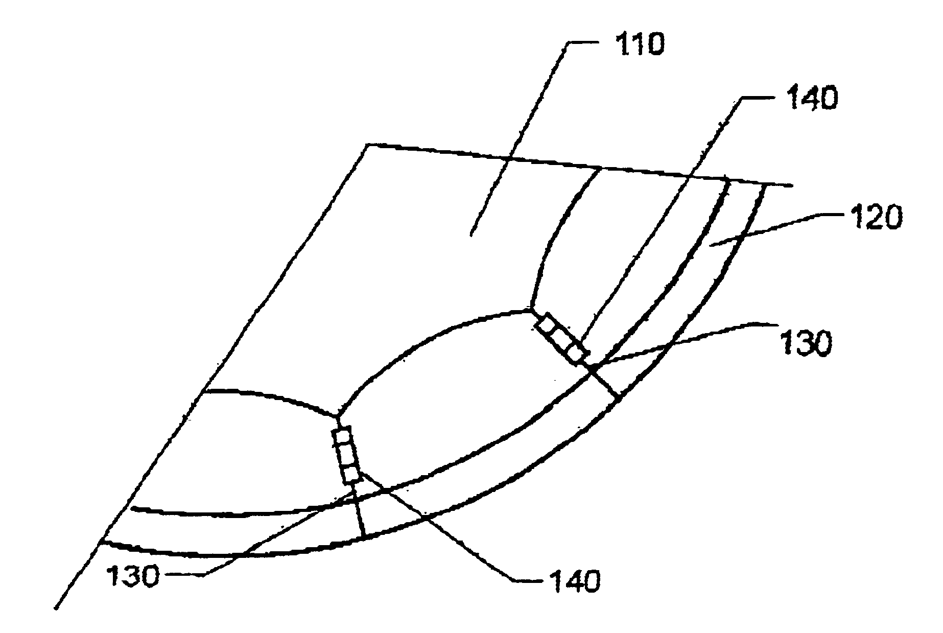
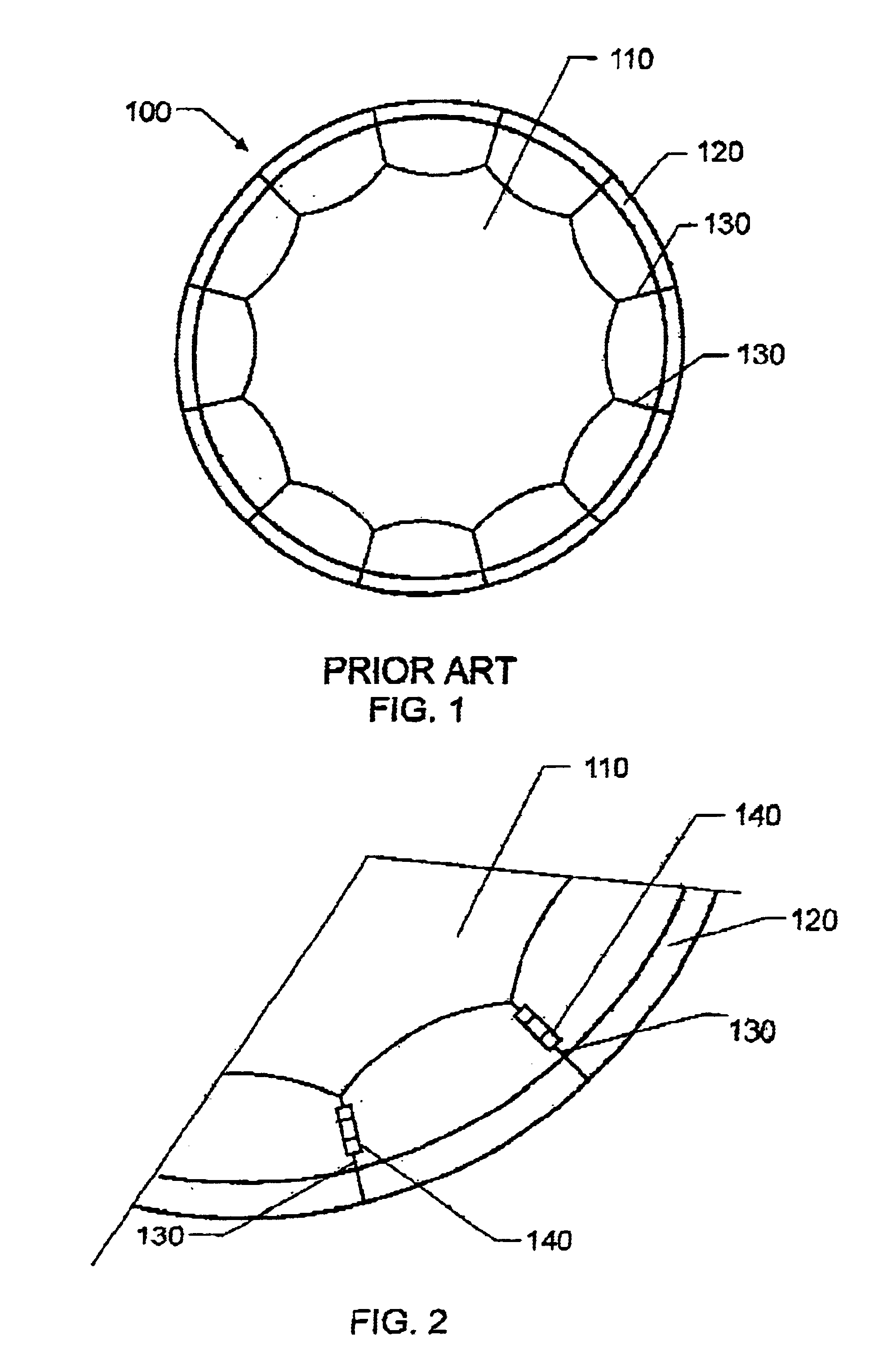
Referring now to the drawings, and more particularly to FIG. 1, a prior art multifunctional membrane structure is shown and referenced generally by the numeral 100. Membrane 110 is connected to supporting frame 120 by threads 130. The threads 130 are generally a metallic material. FIG. 1 is a general representation of a membrane structure; however, the exact shape of the membrane and supporting structure may vary from that shown. FIG. 2 illustrates electrostrictive polymer actuators 140 integrated into threads 130. The actuators 140 expand or contract along the axis of the threads, thereby increasing or decreasing tension in the threads to make local adjustments to maintain the membrane surface in working condition. An actuator 140 can be integrated into one or more threads 130 as desired.

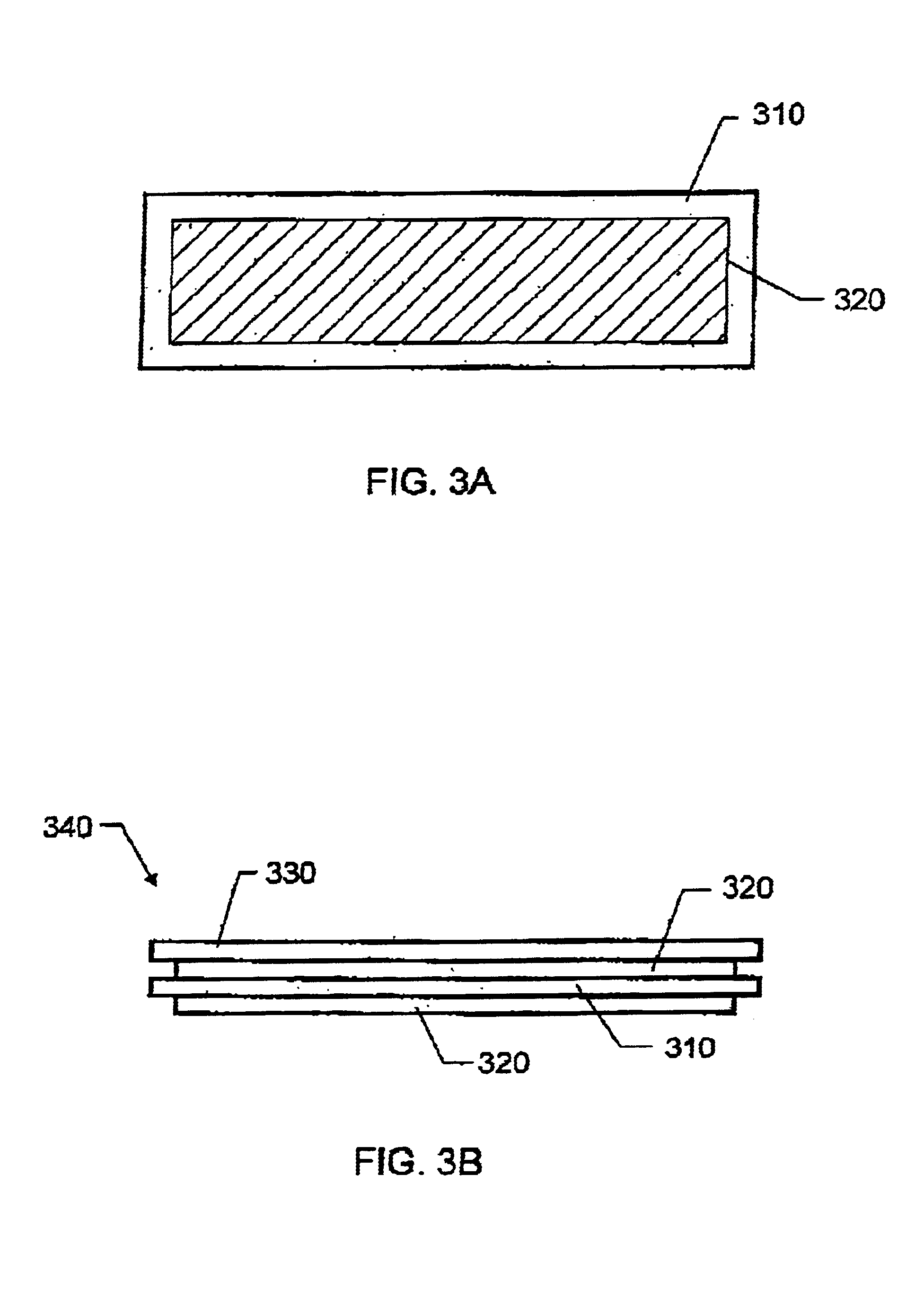
Referring now to FIGS. 3A and 3B, actuator 140 comprises layer 310 of an electrostrictive polymer material having a tailorable Poisson's ratio. The strain in layer 310 increases in one direction as...


PUM

PropertyMeasurementUnit
tensionaaaaaaaaaa
Poisson's ratioaaaaaaaaaa
flexibleaaaaaaaaaa

Abstract

An electrostrictive polymer actuator comprises an electrostrictive polymer with a tailorable Poisson's ratio. The electrostrictive polymer is electroded on its upper and lower surfaces and bonded to an upper material layer. The assembly is rolled tightly and capped at its ends. In a membrane structure having a membrane, a supporting frame and a plurality of threads connecting the membrane to the frame, an actuator can be integrated into one or more of the plurality of threads. The electrostrictive polymer actuator displaces along its longitudinal axis, thereby affecting movement of the membrane surface.

Description

BACKGROUND OF THE INVENTION1. Field of the InventionThe present invention is generally related to tension control of membranes using an electroactive actuator having at least predominantly single axis displacement.2. Description of the Related ArtMembrane inflatable and deployable space structures are widely employed by the government and commercially as reflectors, antennas, solar arrays, satellites, solar sails, etc. Although these membrane inflatable and deployabe structures are widely used, many challenges exist which limit their performance for high precision applications. Factors affecting precision include surface smoothness, deviation from desired surface profile, surface deformations due to thermal fluctuations, and accurate membrane positioning. Actuation devices are used for many applications, including the shaping, tuning, positioning, controlling and deforming of membrane structures. To operate most effectively in the aforementioned applications, actuation devices requi...

Claims


Application Information

Patent Timeline
Patent Type & Authority Patents(United States)
IPC IPC(8): C08F255/00C08F283/12C08F259/00C08F255/10C08F265/08C08F265/00C08F259/08C08F273/00C08F283/00H01L41/18H01L41/09H01L41/00H01Q15/14H01L41/193H01L41/053H10N30/20H10N30/857H10N30/88
CPCC08F255/10C08F259/00C08F259/08C08F265/08C08F273/00H01L41/0836C08F283/12H01L41/053H01L41/193H01Q15/147C08F283/006Y10S310/80H10N30/506H10N30/88H10N30/857
Inventor SU, JIHARRISON, JOYCELYN S.
Owner NASA
Learn More