High pressure discharge lamp and method for producing the same

Inactive Publication Date: 2005-03-15
PANASONIC CORP
View PDF51 Cites 3 Cited by
  • Summary
  • Abstract
  • Description
  • Claims
  • Application Information

AI Technical Summary

Benefits of technology

[0048]The present invention can provide a high pressure discharge lamp exhibiting better characteristics (e.g., high strength against pressure, long life) than those of a conventional high pressure discharge lamp. When at least one metal selected from the group consisting of Pt, Ir, Rh, Ru, and Re is present in the luminous bulb, a high pressure discharge lamp having a long life in which blackening can be effectively prevented from occurring can be provided. When a metal film made of at least one metal selected from the group consisting of Pt, Ir, Rh, Ru, and Re is formed on the surface of at least a part of the portion of the electrode that

Problems solved by technology

However, a high pressure discharge lamp having a significantly high strength agains

Method used


Image

  • High pressure discharge lamp and method for producing the same
  • High pressure discharge lamp and method for producing the same
  • High pressure discharge lamp and method for producing the same

Examples


Example

[0069]Embodiment 1

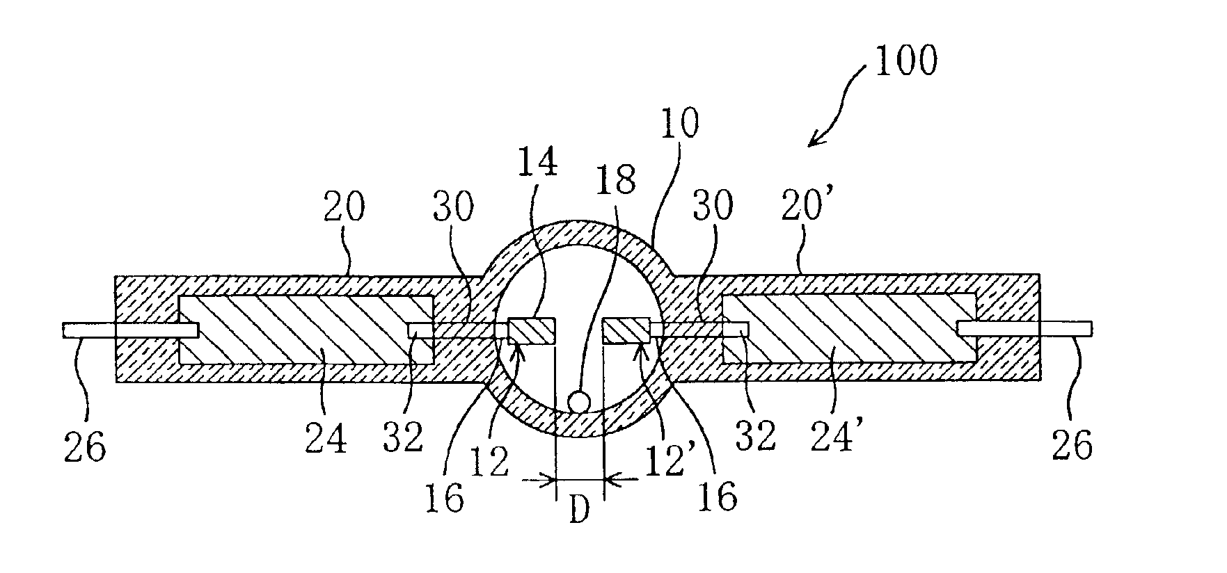
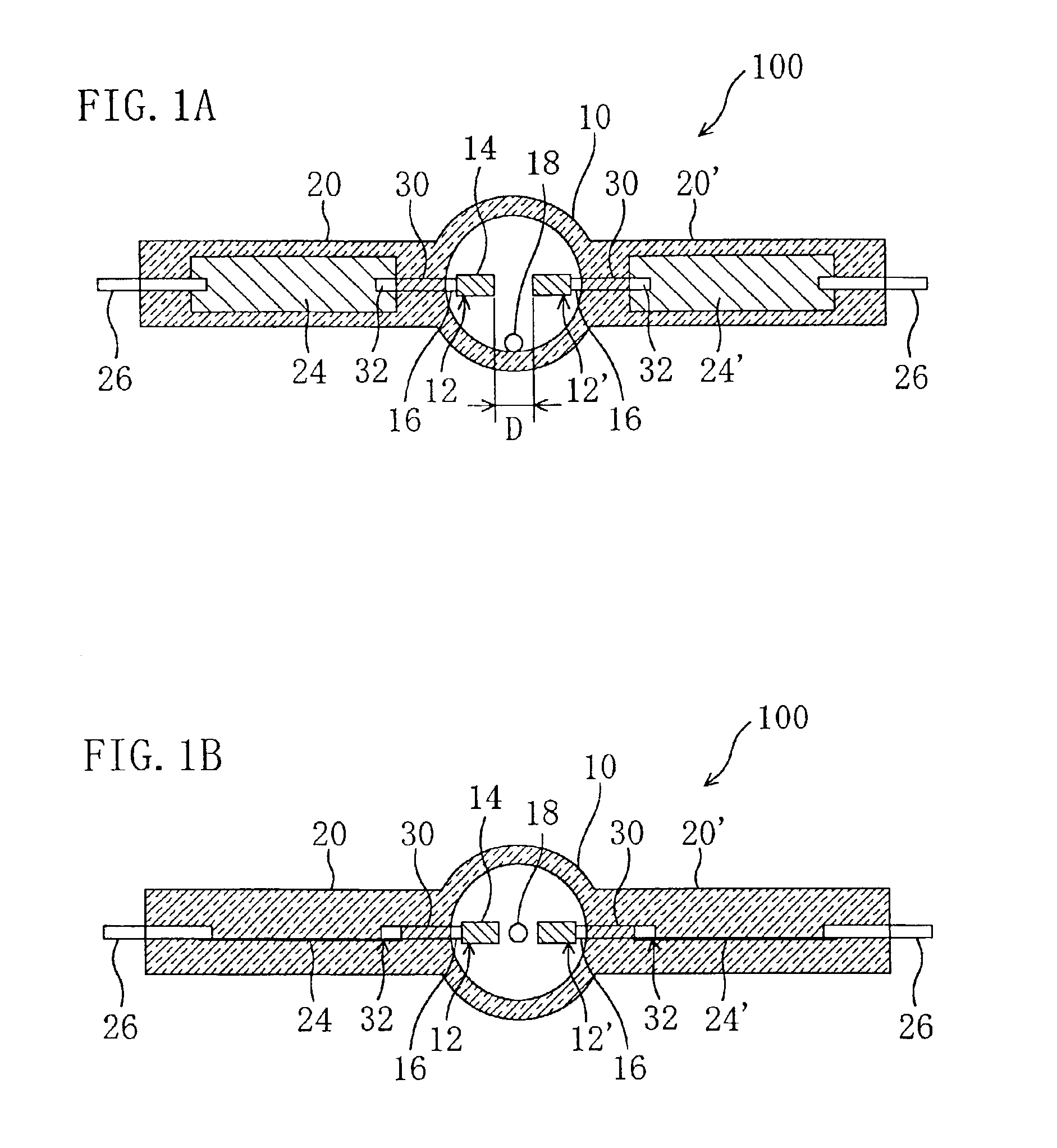
[0070]FIGS. 1A and 1B are schematic views showing the cross-sectional structure of a high pressure discharge lamp of this embodiment. FIG. 1A is a plan view, and FIG. 1B is a side view.

[0071]A lamp 100 includes a luminous bulb 10 in which a pair of electrodes (12, 12′) are opposed inside the bulb, and a pair of sealing portions 20 and 20′ connected to the luminous bulb 10. The luminous bulb 10 is made of quartz glass, and the glass portions of the sealing portions (20, 20′) are extending from the luminous bulb 10. A portion (base portion) of the electrodes (12, 12′) is buried in the sealing portions (20, 20′), and a metal film 30 made of at least one metal selected from the group consisting of Pt, Ir, Rh, Ru, and Re is formed on a surface of at least a part of the portion of the electrodes (12, 12′) that is buried in the sealing portions (20, 20′). In this embodiment, the metal film 30 containing Pt is formed by plating in a portion of the electrodes (12, 12), and ...

Example

[0116]Embodiment 2

[0117]Referring to FIG. 6, a high pressure discharge lamp 300 of Embodiment 2 according to the present invention will be described. FIG. 6 is a schematic view showing the structure of the lamp 300.

[0118]The lamp 300 of this embodiment is different from the lamp 100 of Embodiment 1 in that a coil 40 whose surface is coated with Pt is wound around a portion of the electrode rod 16 that is positioned in the sealing portions (20, 20′) in the lamp 300, as opposed to the lamp 100 where the surface of the electrode rod 16 that is positioned in the sealing portions (20, 20′) is coated with Pt. Other aspects are basically the same as in the structure of the lamp 100. For simplification of the description of this embodiment and the following embodiments, different aspects from in Embodiment 1 are mainly described and the same aspects as in Embodiment 1 are omitted or simplified.

[0119]The coil 40 in the lamp 300, is for example, a tungsten coil whose surface is placed with Pt...

Example

[0130]Embodiment 3

[0131]Referring to FIG. 11, a high pressure discharge lamp 400 of Embodiment 3 according to the present invention will be described. FIG. 11 is a schematic view showing the structure of the lamp 400.

[0132]The lamp 400 of this embodiment is different from the lamp 100 of Embodiment 1 in that a region 21 containing vycor glass is formed inside the sealing portions (20, 20′) over the portion in which the electrode rods 16 and the metal foils (24, 24′) are positioned. In other words, the lamp 400 of this embodiment has a structure in which the region 21 containing vycor glass is formed inside the sealing portions (20, 20′) so as to cover a portion of the electrode rods 16 having the metal film 30 on its surface and a portion of the metal foils (24, 24′). In this structure, the periphery of the welded portion 32 is also covered with the region 21.

[0133]Vycor glass (product name) refers to glass having a reduced softening point by mixing an additive with quartz glass and...


PUM


Abstract

A high pressure discharge lamp includes a luminous bulb in which a pair of electrodes are opposed to each other in the bulb. At least mercury and halogen are contained in the luminous bulb, and at least one metal selected from the group consisting of Pt, Ir, Rh, Ru and Re is present in the luminous bulb.

Description

BACKGROUND OF THE INVENTION[0002]The present invention relates to a high pressure discharge lamp and a method for producing the same. In particular, the present invention relates to a high pressure discharge lamp used for general illumination or other applications such as projectors and headlights of automobiles when it is used in combination with a reflecting mirror.[0003]In recent years, an image projection apparatus such as a liquid crystal projector and a DMD projector has been widely used as a system for realizing large-scale screen images, and a high pressure discharge lamp having a high intensity has been commonly and widely used in such an image projection apparatus. FIG. 14 is a schematic view showing the structure of a conventional high pressure discharge lamp 1000. The lamp 1000 is a so-called ultra-high pressure mercury lamp.[0004]The lamp 1000 includes a luminous bulb 110 made of quartz glass, and a pair of sealing portions 120 (seal portions) extending from both ends o...

Claims


Application Information

Patent Timeline
IPC IPC(8): H01J9/32H01J61/12H01J9/24H01J61/26H01J61/36H01J61/82
CPCH01J9/247H01J9/326H01J61/82H01J61/366H01J61/26H01J61/12
Inventor TAKAHASHI, KIYOSHIKANEKO, YURIKOHORIUCHI, MAKOTOSEKI, TOMOYUKIICHIBAKASE, TSUYOSHIHATAOKA, SHINICHIRO
Owner PANASONIC CORP
Why Eureka
Try Eureka