Radio communication system with request re-transmission until acknowledged

Inactive Publication Date: 2005-03-15
UNILOC 2017 LLC
View PDF12 Cites 77 Cited by
  • Summary
  • Abstract
  • Description
  • Claims
  • Application Information

AI Technical Summary

Benefits of technology

The present invention is based upon the recognition, not present in the prior art, that in a system having time slots allocated to a secondary statio

Problems solved by technology

However, if there is no uplink channel assigned to the MS piggy-backing is not possible.
However, such a scheme works satisfactorily only with a low

Method used


Image

  • Radio communication system with request re-transmission until acknowledged
  • Radio communication system with request re-transmission until acknowledged
  • Radio communication system with request re-transmission until acknowledged

Examples


Embodiment Construction

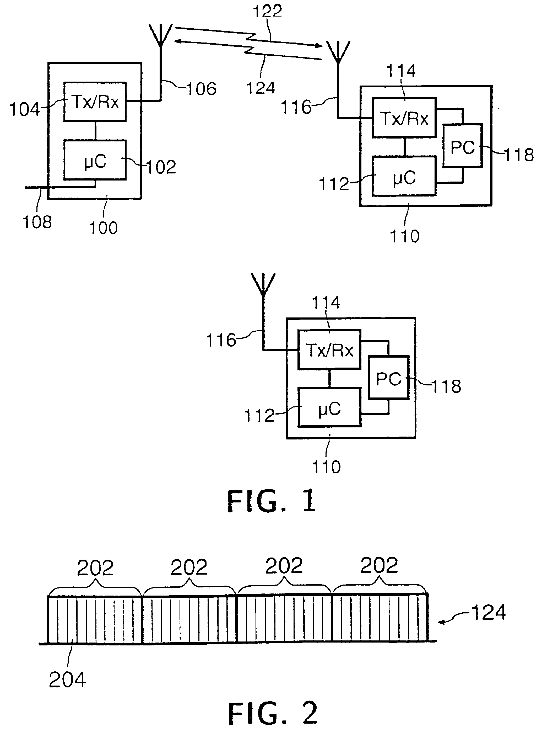
Referring to FIG. 1, a radio communication system comprises a fill primary station (BS) 100 and a plurality of secondary stations (MS) 110. The BS 100 comprises a microcontroller (μC) 102, transceiver means 104 connected to radio transmission means 106, and connection means 108 for connection to the PSTN or other suitable network. Each MS 110 comprises a microcontroller (μC) 112, transceiver means 114 connected to radio transmission means 116, and power control means 118 for altering the transmitted power level. Communication from BS 100 to MS 110 takes place on a downlink channel 122, while communication from MS 110 to BS 100 takes place on an uplink channel 124.

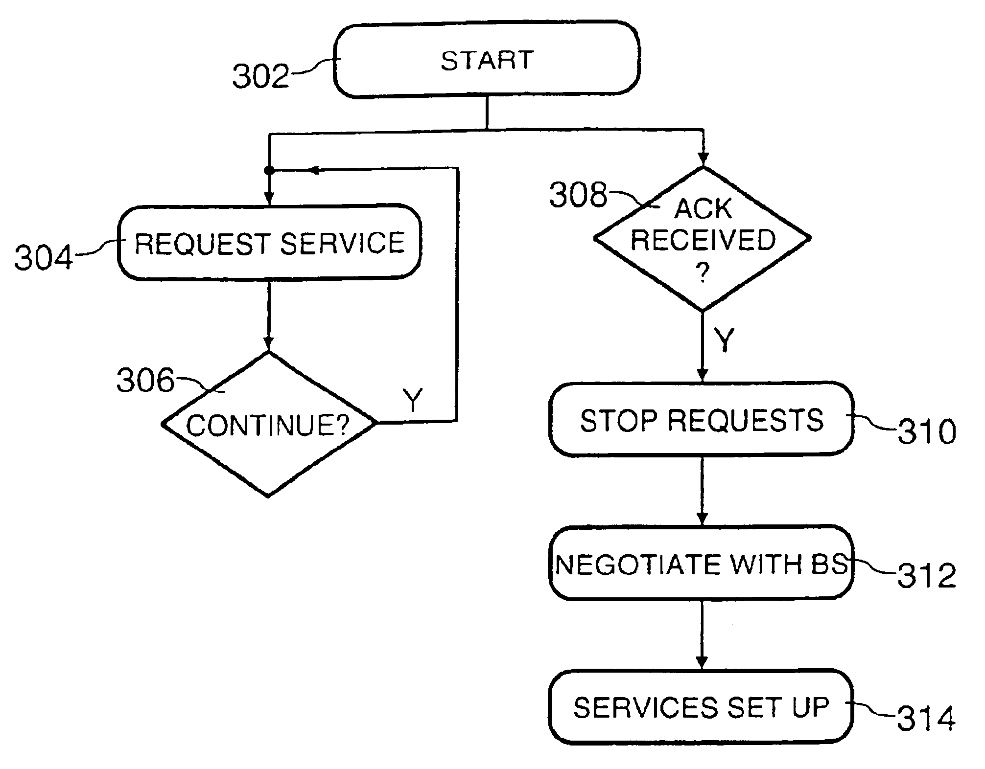
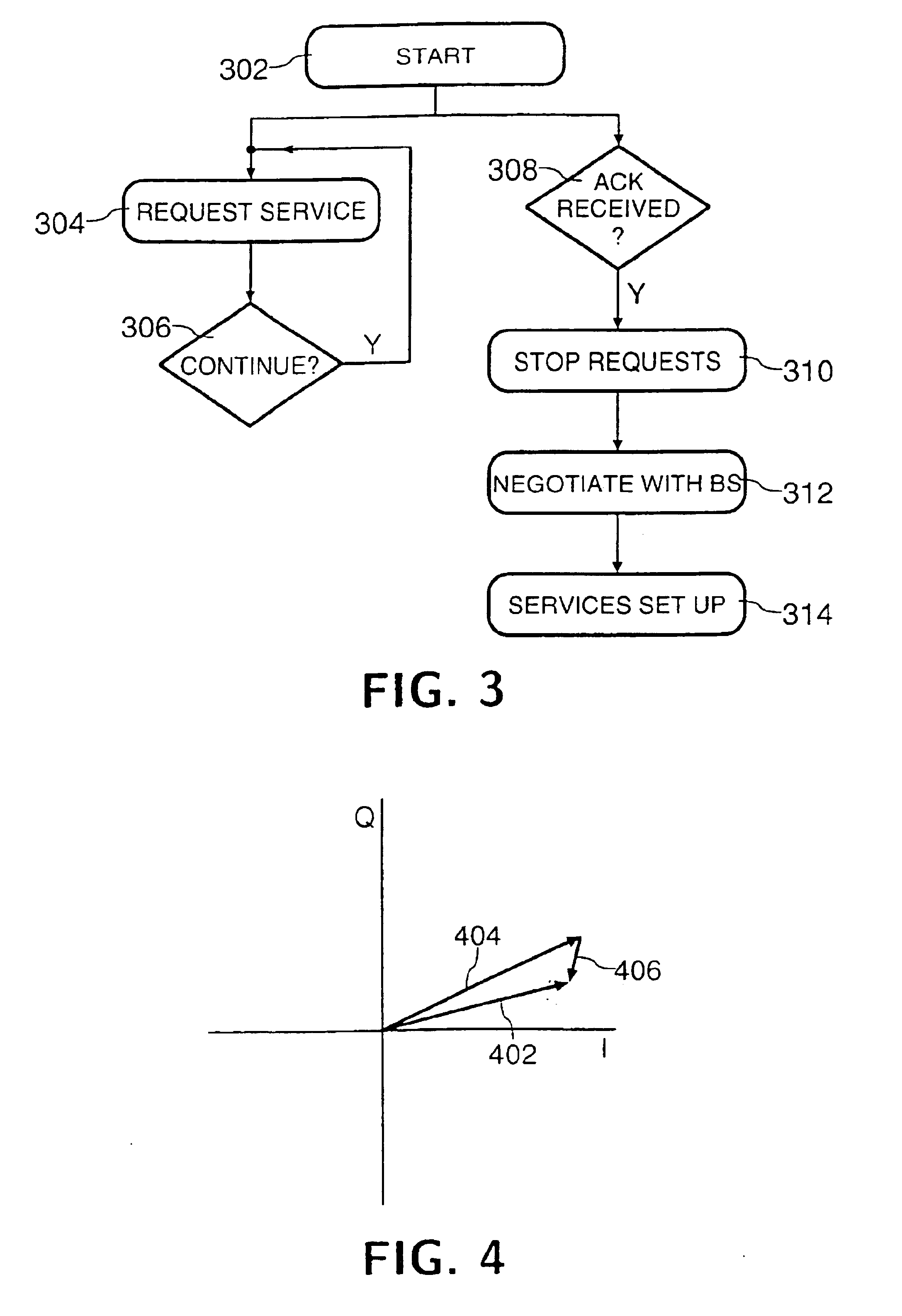
The present invention is concerned with an uplink channel 124 dedicated to the transmission of requests for services by a MS 110 to a BS 100. One arrangement of such a channel for UMTS is illustrated in FIG. 2. The uplink channel 124 is divided into a succession of frames 202, each of length 10 ms, and each MS 110 registere...


PUM


Abstract

A method of operating a radio communication system in which secondary stations use dedicated time slots to request services from a primary station. A secondary station wishing to request a service sends a request in every time slot allocated to it until it receives an acknowledgement from the primary station. The primary station can use combining techniques on multiple time slots to identify the presence or absence of a request from a secondary station with improved accuracy.

Description

FIELD OF THE INVENTIONThe present invention relates to a method of operating a radio communication system, and further relates to such a system and to primary and secondary stations for use in such a system. While the present specification describes a system with particular reference to the emerging Universal Mobile Telecommunication System (UMTS), it is to be understood that such techniques are equally applicable to use in other mobile radio systems.BACKGROUND OF THE INVENTIONIn a radio communication system it is generally required to be able to exchange signalling messages between a Mobile Station (MS) and a Base Station (BS). Downlink signalling (from BS to MS) is usually realised by using a physical broadcast channel of the BS to address any MS in its coverage area. Since only one transmitter (the BS) uses this broadcast channel there is no access problem.In contrast, uplink signalling (from MS to BS) requires more detailed considerations. If the MS already has an uplink channel...

Claims


Application Information

Patent Timeline
IPC IPC(8): H04Q7/38H04J3/16H04L12/28H04L12/56H04W28/04H04W72/04H04W74/04
CPCH04W74/004H04L1/1867H04W28/04H04W74/04H04W72/0446
Inventor HUNT, BERNARD
Owner UNILOC 2017 LLC
Why Eureka
Try Eureka