
Method for making a transducer

a transducer and piezoelectric technology, applied in the field of composite piezoelectric transducer elements, can solve the problems of not solving the problem of acoustic matching, reducing the open-circuit sensitivity, and achieving good electrical impedance match, so as to increase the number of layers, and reduce the open-circuit sensitivity

Inactive Publication Date: 2005-03-22
GUARDIAN IND CORP
View PDF6 Cites 36 Cited by
  • Summary
  • Abstract
  • Description
  • Claims
  • Application Information

AI Technical Summary

Benefits of technology

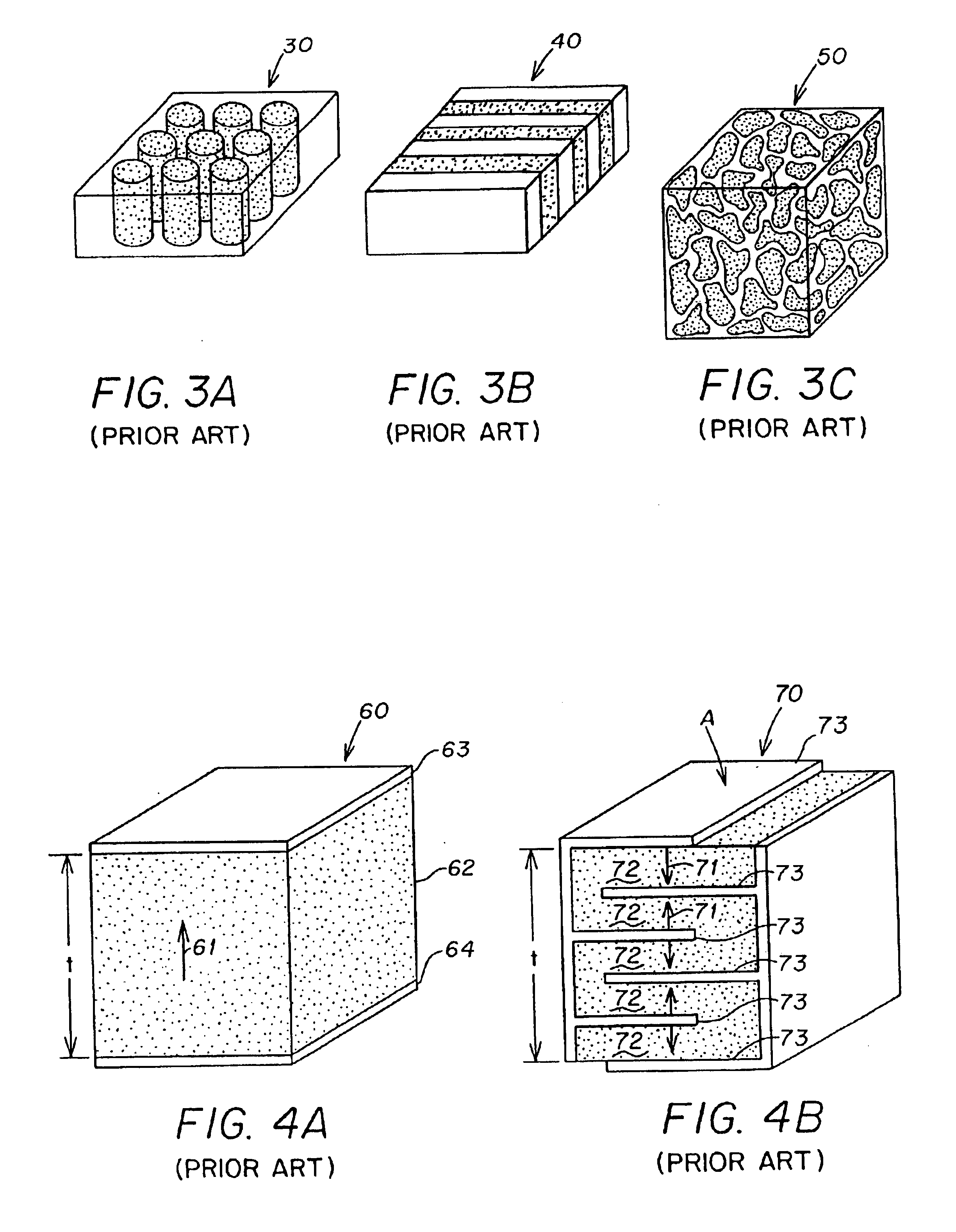
where Csingle is the capacitance of a single layer transducer (such as element 60 in FIG. 4A having a single ceramic layer 62 between electrodes 63, 64). As described in Goldberg et al., the open-circuit receive sensitivity is directly proportional to the layer thickness t / N, and as a result increasing the number of layers will decrease the open-circuit sensitivity. However, the authors state that the multilayer ceramic structure's ability to drive an electrical load compensates for the decreased open-circuit sensitivity.
While the multilayer ceramic structure of Goldberg et al. lowers the electrical impedance of an array element for better power transfer with the imaging system, it does not solve the problem of acoustic matching. Furthermore, while 2-D arrays are desirable in providing elements along the azimuth and elevation planes to provide dynamic control of the ultrasound beam in both directions, the smaller size of the array elements increases the electrical impedance, and thus exacerbates the problem of poor transducer sensitivity. Thus, none of the prior art systems effectively provide both a good match of acoustical impedance to the medium being observed, and a good match of electrical impedance of the imaging system, especially for extremely small transducer elements as required in phased arrays and 2-D matrix arrays.

Problems solved by technology

However, there is still a problem in achieving a good match of electrical impedance.
As described in Goldberg et al., the open-circuit receive sensitivity is directly proportional to the layer thickness t / N, and as a result increasing the number of layers will decrease the open-circuit sensitivity.
While the multilayer ceramic structure of Goldberg et al. lowers the electrical impedance of an array element for better power transfer with the imaging system, it does not solve the problem of acoustic matching.
Furthermore, while 2-D arrays are desirable in providing elements along the azimuth and elevation planes to provide dynamic control of the ultrasound beam in both directions, the smaller size of the array elements increases the electrical impedance, and thus exacerbates the problem of poor transducer sensitivity.
Thus, none of the prior art systems effectively provide both a good match of acoustical impedance to the medium being observed, and a good match of electrical impedance of the imaging system, especially for extremely small transducer elements as required in phased arrays and 2-D matrix arrays.
One of the major problems in 2-D arrays is that element sizes are very tiny which results in extremely large electrical impedance.
Thus, the impedance of each of the 2-D array elements is at least 64 times larger and makes it difficult to couple the electrical energy from the typically 50 ohm imaging system to the transducer.

Method used


Image

  • Method for making a transducer
  • Method for making a transducer
  • Method for making a transducer

Examples


Embodiment Construction

A block diagram of a phased-array, pulse-echo ultrasound imaging system 100 is shown in FIG. 5A. The system provides a pulsed electrical stimulus to an array of transducers 101, which causes the transducers to transmit an ultrasonic acoustical wave 103. The wave is transmitted into a medium, such as a human body, and eventually, at least partially reflected by an object (e.g., heart 115) in the medium. The reflected wave (the “echo”) is received by the transducers 101, which produce an electrical signal 104 that is indicative of the echo. Various properties of the electrical signal caused by the echo, such as its amplitude and phase, are then analyzed by a signal processing section of the imaging system to determine information about the object, such as its size, location, and velocity. The imaging system may use beam steering, phased array, or other techniques known in the art to stimulate the transducers and to analyze the electrical signal resulting from the echo, see e.g., U.S. ...


PUM

PropertyMeasurementUnit
electric impedanceaaaaaaaaaa
thicknessaaaaaaaaaa
distanceaaaaaaaaaa

Abstract

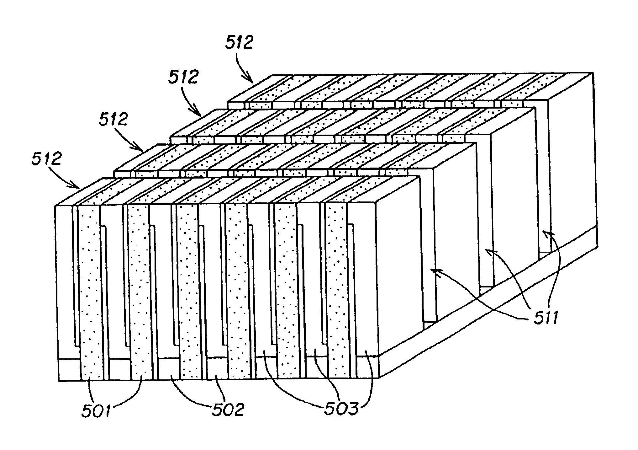
A method for producing transducers having a 1-3 composite structure. The transducer element includes a plurality of thin piezoceramic wafers which are electroded on opposing major surfaces. The spaced wafers are separated by a passive polymer layer in a composite structure and the electrodes on the opposing major surfaces are connected to different ones of top and bottom electrode surfaces.

Description

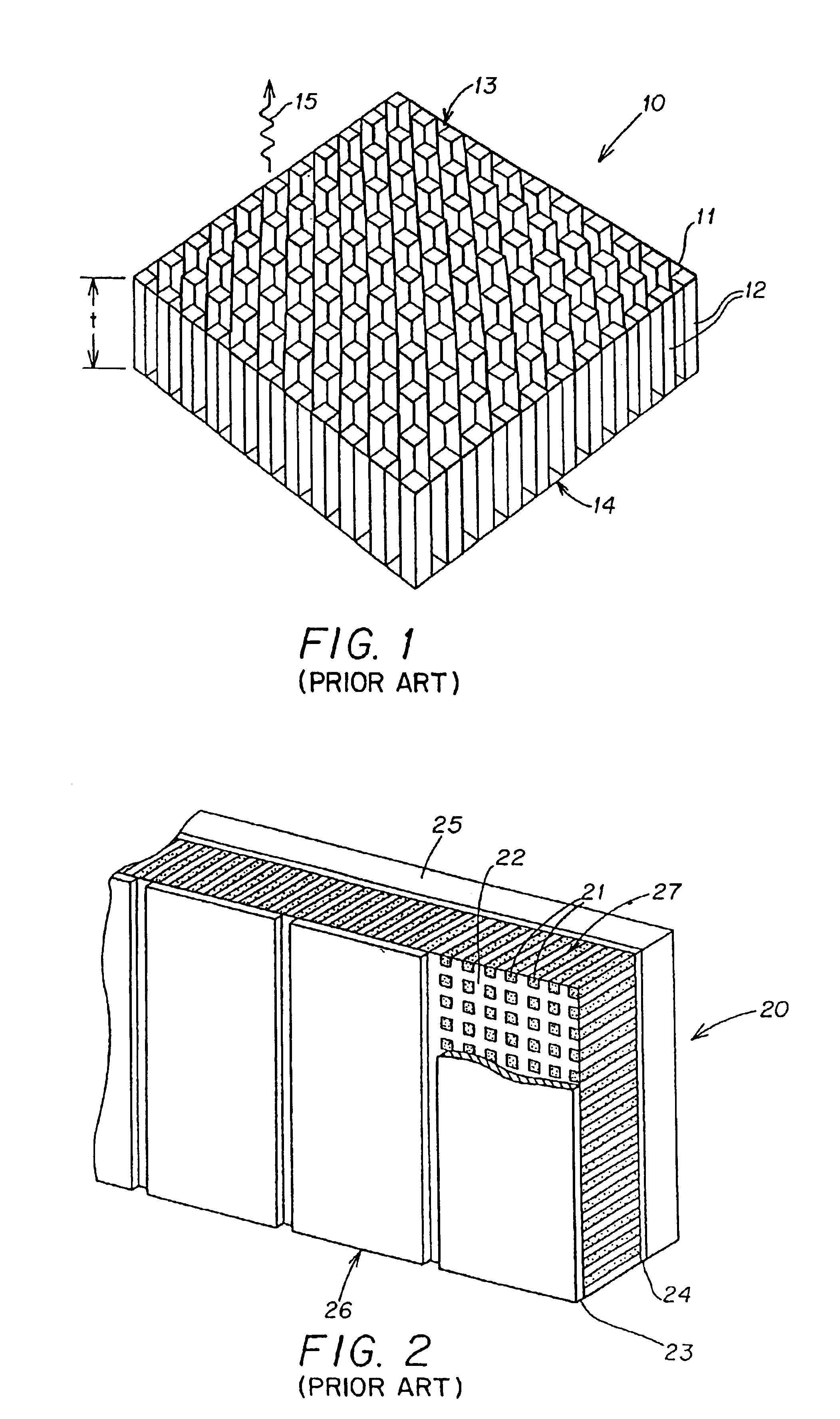
FIELD OF THE INVENTIONThis invention relates to transducer elements used in transducer arrays, such as linear arrays, phased arrays, and two-dimensional arrays, and more particularly to a composite piezoelectric transducer element having a good match of both acoustical impedance with the body and electrical impedance with the imaging system.BACKGROUND OF THE INVENTIONAcoustic transducers for medical ultrasonic imaging are made of piezoelectric materials. A variety of composite materials are made by combining a piezoelectric ceramic with a passive polymer phase. These composite materials extend the range of material properties offered by conventional piezoelectric ceramics and polymers.In pulse-echo medical ultrasonic imaging, a 1-3 composite geometry has been identified as the most promising. W. A. Smith, “Composite Piezoelectric Materials For Ultrasonic Imaging Transducers—A Review,” 1986 IEEE, CH2358-0 / 86 / 0000 / 0249, pages 249-255. For example, the 1-3 PZT rod-polymer composite str...

Claims


Application Information

Patent Timeline
Patent Type & Authority Patents(United States)
IPC IPC(8): B06B1/06H01L41/22H10N30/01
CPCB06B1/0622H01L41/37H01L41/183Y10T29/49128Y10T29/4908Y10T29/42Y10T29/49798Y10T83/2079Y10T83/0457Y10T83/0538H10N30/852H10N30/092
Inventor GURURAJA, TURUKEVERE R.
Owner GUARDIAN IND CORP
Learn More