Charged air intake system for an internal combustion engine

a technology of internal combustion engine and air intake system, which is applied in the direction of electric ignition installation, machines/engines, mechanical equipment, etc., can solve the problems of corroding sulfuric acid in the intake system, and excessive heating of intake air, etc., to achieve the effect of increasing the density of air flowing

Inactive Publication Date: 2005-03-22
DETROIT DIESEL CORP
View PDF68 Cites 47 Cited by
  • Summary
  • Abstract
  • Description
  • Claims
  • Application Information

AI Technical Summary

Benefits of technology

In accordance with one aspect of the invention, a charge air intake system for an internal combustion engine, preferably a diesel engine, includes an air intake plenum for furnishing air to the engine, a first air supply duct for furnishing air to the intake plenum, a charge air cooler mounted in line with the first air supply duct for removing heat from air flowing though the first air supply duct, a second air supply duct for furnishing air to the intake plenum having an upstream junction with the first air supply duct upstream from...

Problems solved by technology

The intake air may, however, be excessively heated during the charging process.
The condensation becomes a more serious issue in diesel engines that utilize exhaust gas recirculation.
The condensation and formation of sulfuric acid has a corrosive effect on the intake system.
If the sulfuric acid is introduced into the engine, it can detrimentally act on the cylinder walls and piston rings and produce overall increased engine wear.
While proposed solutions h...

Method used


Image

  • Charged air intake system for an internal combustion engine
  • Charged air intake system for an internal combustion engine

Examples


Embodiment Construction

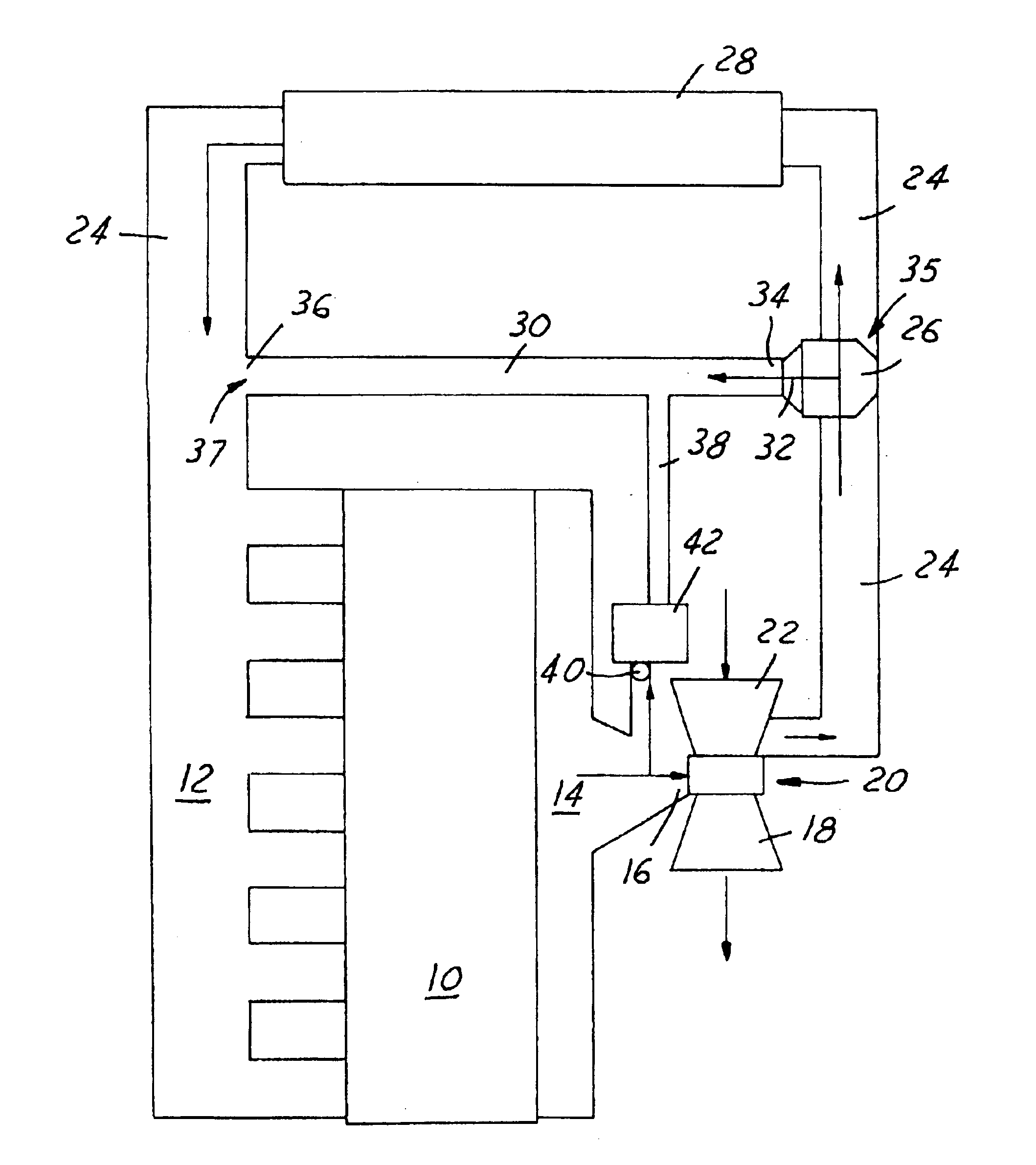
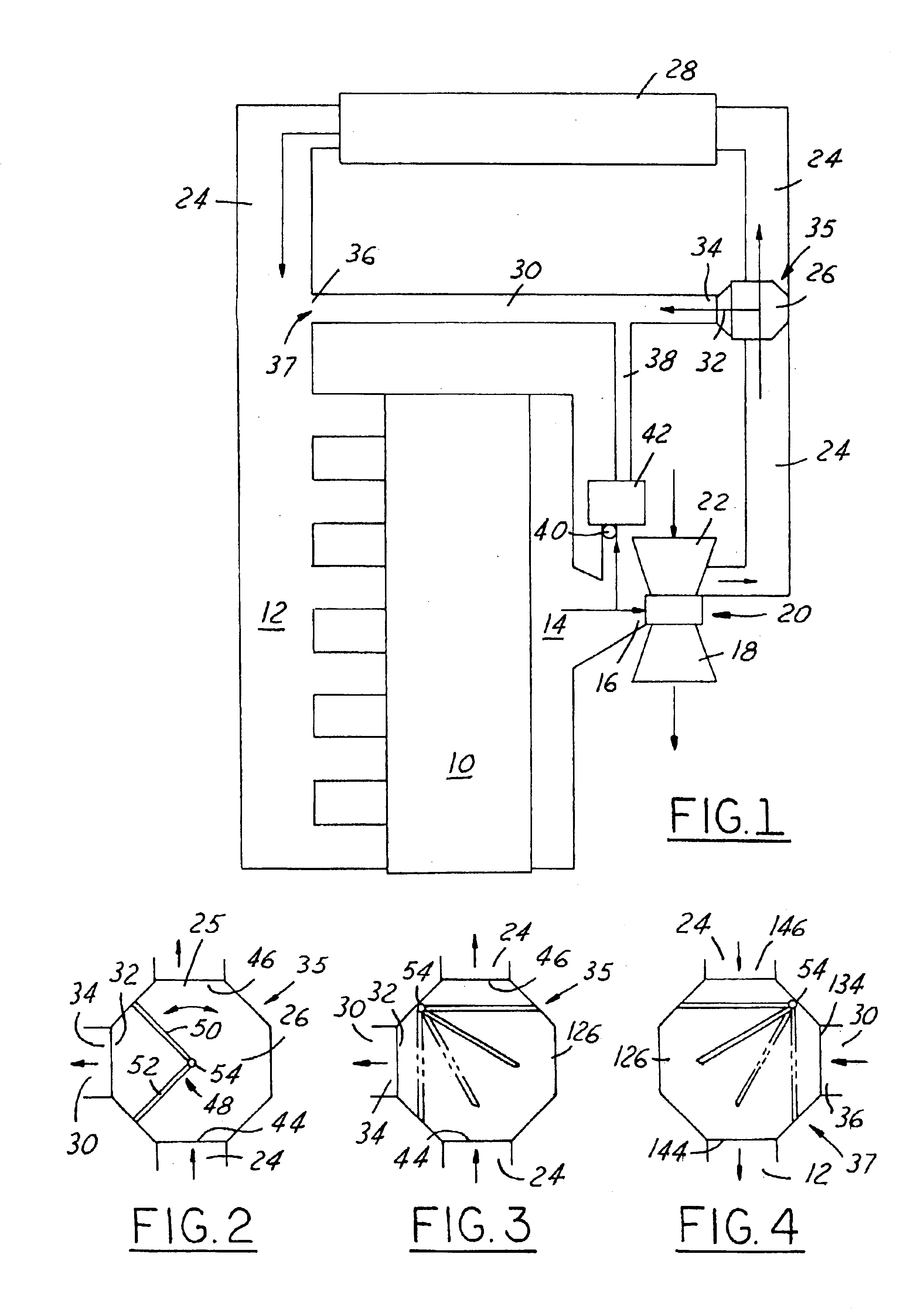
Referring now to FIG. 1, a diesel engine 10 has a conventional intake manifold 12 and exhaust manifold 14. The exhaust manifold has a pipe section 16 leading to a turbo charger exhaust impeller section 18 of turbocharger 20. An intake impeller section 22 is driven and charges fresh air into intake duct 24.

Intake duct 24 has a proportioning valve 26 mounted therein and a charge air cooler 28 downstream of the valve 26. Valve 26 has a second outlet 32 leading to a second or bypass duct 30. In other words, bypass duct 30 has it upstream end 34 in communication with duct 24 upstream of charge air cooler 2B. In addition, bypass duct 30 has its downstream end 36 connecting with first duct 24 downstream of charge air cooler 28 leading to the intake manifold 12. These upstream and downstream junctions are labeled 35 and 37.

The exhaust manifold also has an EGR valve 40 leading to an EGR cooler 42 which leads to EGR duct 38. Duct 38 is connected to bypass duct 30 for delivery the EGR gasses t...


PUM


Abstract

A charge air intake system for a diesel engine (10) includes a first duct (24) and second bypass duct (30) having its upstream and downstream ends connected to the first duct and bypassing a charge air cooler (28) mounted in line with the first duct (24). An EGR conduit (38) leads from the exhaust manifold to the bypass duct (30). A turbo charger furnished charged air to the ducts where a proportioning valve (26) proportions air between the charge air cooler and the bypass duct.

Description

TECHNICAL FIELDThe field of this invention relates to a charged air intake system for a compression-ignition internal combustion engine utilizing exhaust gas recirculation and a method for reducing formation of intake condensation.BACKGROUND OF THE DISCLOSURETurbo charging or supercharging the intake air into diesel engines is common place for better performance. The charging of the air provides for greater initial density of the air and thus more air for a more powerful combustion cycle. The intake air may, however, be excessively heated during the charging process. Consequently, charge air coolers are common in diesel engines for taking excess heat out of the intake air to prevent premature compression ignition.Excess cooling of the charged fresh air provides opportunities for condensation to occur in the intake system. The condensation becomes a more serious issue in diesel engines that utilize exhaust gas recirculation. Exhaust gas recirculation is commonly used to reduce engine...

Claims


Application Information

Patent Timeline
IPC IPC(8): F02B29/04F02B37/00F02B29/00F02B3/06F02B3/00F02M25/07
CPCF02B29/0418F02B37/00F02B3/06Y02T10/144F02M25/0727F02M25/0749Y02T10/146F02M25/0707F02M26/05F02M26/23F02M26/43Y02T10/12F02M26/02
Inventor LEWALLEN, BRIAN ANDREW
Owner DETROIT DIESEL CORP
Why Eureka
Try Eureka