Eureka AIR delivers breakthrough ideas for toughest innovation challenges, trusted by R&D personnel around the world.

Method of driving and controlling ink jet print head, ink jet print head, and ink jet printer

a technology of ink jet printer, which is applied in the direction of printing, inking apparatus, other printing apparatus, etc., can solve the problems of inability to accurately control the ink jet print head, the amount of ink ejected is not uniform, and the ink is unstably ejected, so as to improve the efficiency of ejected, increase the resistance value, and increase the cost

Inactive Publication Date: 2005-03-22
CANON KK
View PDF9 Cites 6 Cited by
  • Summary
  • Abstract
  • Description
  • Claims
  • Application Information

AI Technical Summary

Benefits of technology

It is an object of the present invention to deal with an increase in variation in resistance value without increasing costs by allowing smaller ink droplets to be efficiently ejected, the increase resulting from a means for increasing the resistances of heating resistance elements comprises reducing the thickness of heaters, improving the shape thereof to substantially increase the number of sheets, or the like.
Here, the control means can set a lower voltage for the drive signal as the threshold electric energy of the ink jet print head decreases.
The modulating means can less significantly modulate the pulse width based on the conditions used to drive the ink jet print head as the above voltage decreases.
As described above, the present invention provides, for example, an ink jet print head based on a thermal ink jet system, the print head using heating resistance elements that generate heat in response to electric conduction so that growth and contraction of bubbles is utilized to eject ink through nozzles, a setting for a pulse voltage is essentially varied depending on the ejection threshold energy of the head to deal with an increase in variation in resistance value which may occur if a means for reducing the thickness of heaters, improving the shape thereof to substantially increase the number of sheets, or the like. Accordingly, optimum drive power conditions can be reasonably designed to deal with a range of resistance value varying among heads owing to differences among manufactured print heads. Thus, smaller ink droplets can be efficiently ejected without increasing costs to cope with an increase in differences among manufactured heads.

Problems solved by technology

For example, if the drive power is set at a small value relative to a required resistance value, the ink is unstably ejected, i.e., the amount of ink ejected is not uniform.
In contrast, if the drive power is set at a large value, an unnecessarily large amount of power is supplied to the heating resistance elements to reduce the lives of these elements or the print head, thereby possibly degrading the reliability of the print head.
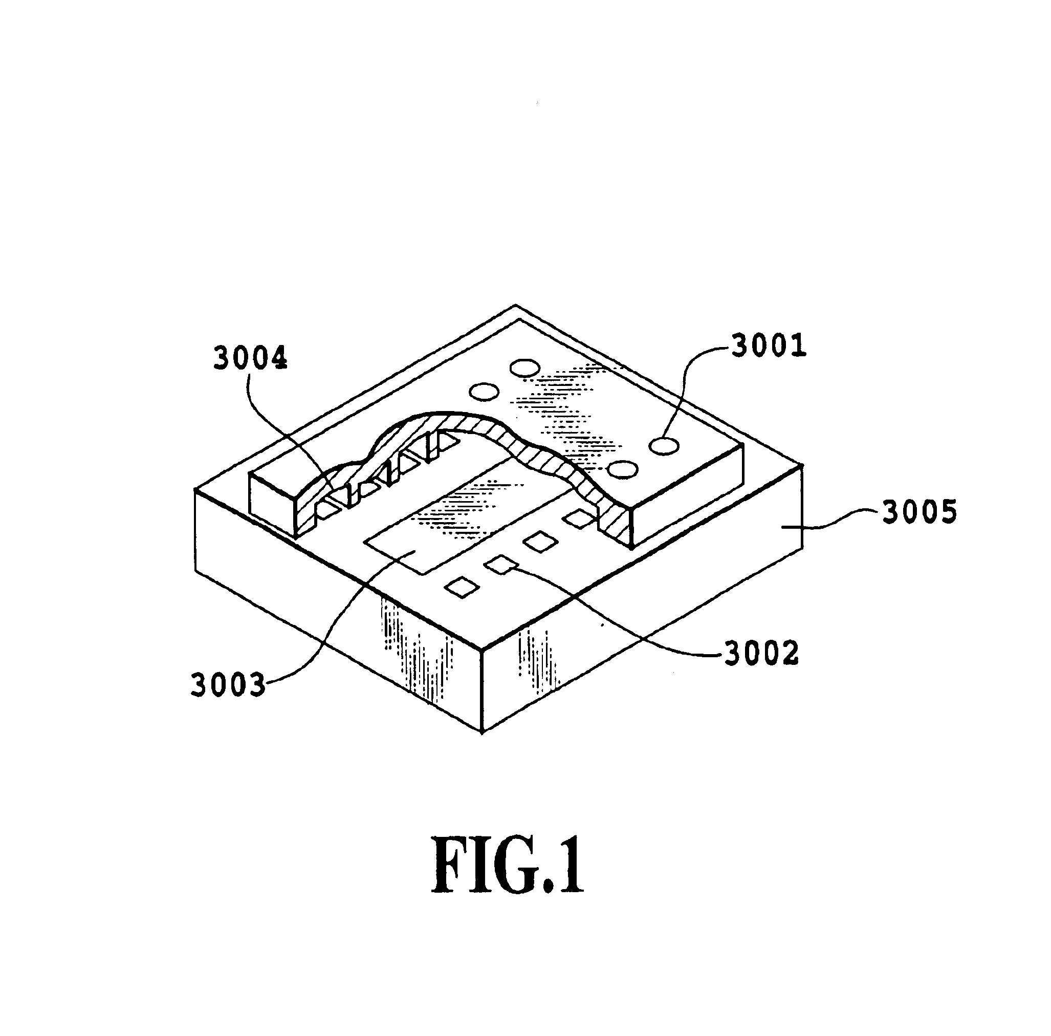
However, if an attempt is made to directly measure the heating resistance elements 3002 of each head, the total resistance value, i.e. the resistance values of each heating resistance element 3002 and functional elements electrically connected thereto, is measured, thereby hindering the resistance value of only the heating resistance element 3002 to be accurately measured.
However, in this case, manufacturing constraints become more severe to increase the variation in resistance value.
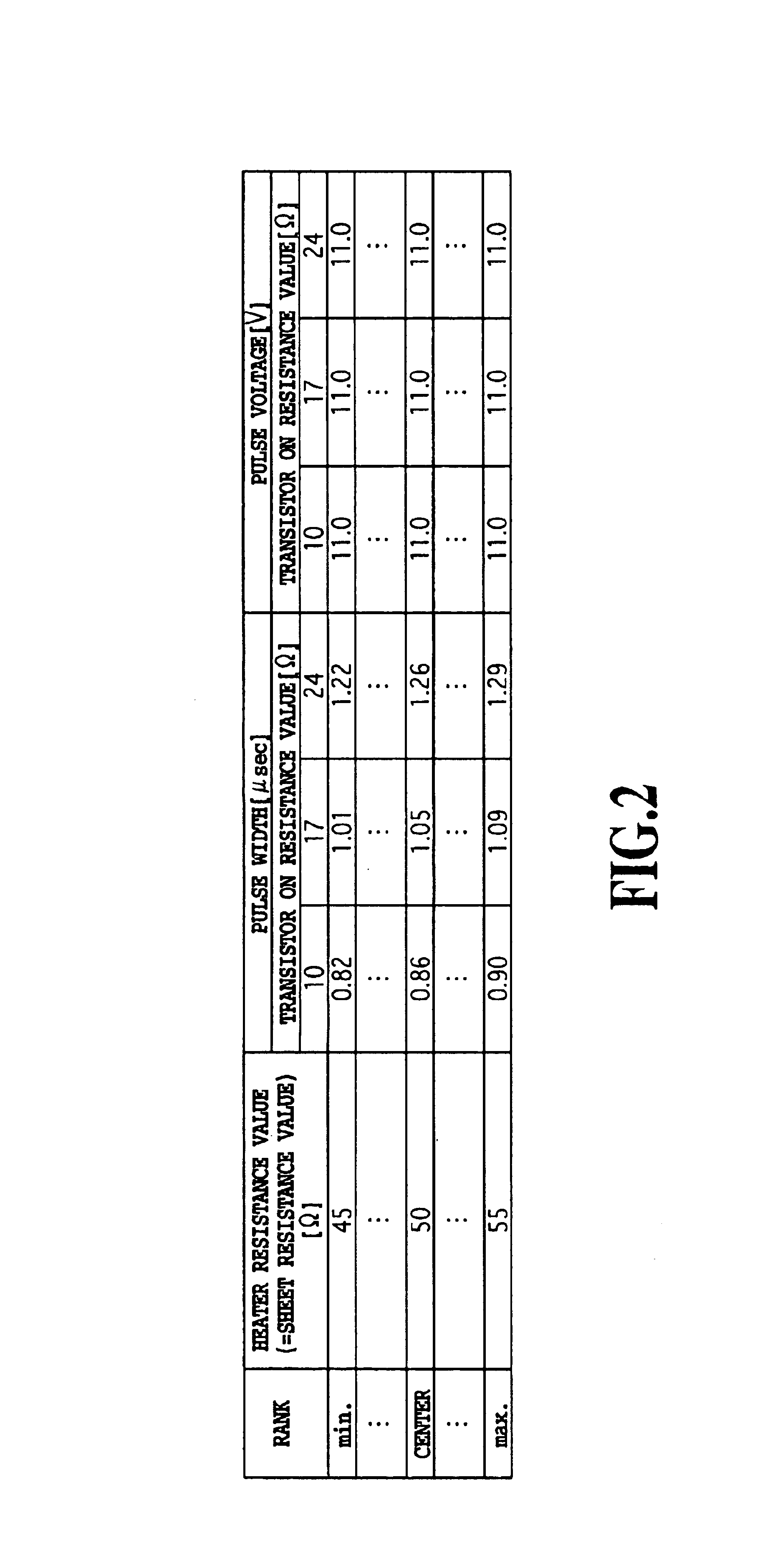
Thus, with the above-described conventional method, print heads with a rank “min.” having the minimum resistance value within a tolerance range have an excessively small pulse width, whereas print heads with a rank “max.” having the maximum resistance value within the tolerance range have an excessively large pulse width.
), it may be very difficult to design the PWM control or K value control in accordance with a variation in temperature or print pattern density.
However, this may reduce the yield of manufactured print heads to sharply increase the costs thereof, so that this method is not a realistic solution.

Method used


Image

  • Method of driving and controlling ink jet print head, ink jet print head, and ink jet printer
  • Method of driving and controlling ink jet print head, ink jet print head, and ink jet printer
  • Method of driving and controlling ink jet print head, ink jet print head, and ink jet printer

Examples


Embodiment Construction

The present invention will be described below in detail with reference to the drawings.

1. Apparatus Body

FIGS. 3 and 4 show an outline construction of a printing apparatus using an ink jet printing system. In FIG. 3, a housing of a printing apparatus body M1000 of the printing apparatus according to this embodiment has an enclosure member, including a lower case M1001, an upper case M1002, an access cover M1003 and a discharge tray M1004, and a chassis M3019 (see FIG. 4) accommodated in the enclosure member.

The chassis M3019 is made of a plurality of plate-like metal members with a predetermined rigidity to form a skeleton of the printing apparatus and holds various printing operation mechanisms described later.

The lower case M1001 forms roughly a lower half of the housing of the printing apparatus body M1000 and the upper case M1002 forms roughly an upper half of the printing apparatus body M1000. These upper and lower cases, when combined, form a hollow structure having an accommod...


PUM


Abstract

An increase in variation in resistance value resulting from a reduction in thickness of heaters is dealt with without increasing the manufacture costs of the print head, by allowing smaller ink droplets to be efficiently ejected. A setting for a pulse voltage essentially varied depending on the ejection threshold energy of the head is employed so that optimum drive power conditions can be reasonably set over a range of varying resistance values resulting from differences among manufactured print heads. This provides a print head and a printing apparatus which can deal with an increase in differences among manufactured heads by allowing smaller ink droplets to be efficiently ejected without reducing the yield of manufactured print heads.

Description

This application is based on Patent Application No. 2001-088453 filed Mar. 26, 2001 in Japan, the content of which is incorporated hereinto by reference.BACKGROUND OF THE INVENTION1. Field of the InventionThe present invention relates to a method of driving and controlling an ink jet print head, an ink jet print head applied to this method, and a printing apparatus using this method. Specifically, the present invention relates to an ink jet print head and printing apparatus based on a thermal ink jet system in which heating resistance elements that generate heat in response to electric conduction are used to cause film boiling in ink so that growth and contraction of the resulting bubbles is used to eject the ink through nozzles.2. Description of the Related ArtIn recent years, ink jet printing systems have advanced rapidly because they can achieve high-density and high-definition printing at a high speed to promptly provide high-quality print matter and are suitable for multicolor ...

Claims


Application Information

Patent Timeline
Patent Type & Authority Patents(United States)
IPC IPC(8): B41J2/05B41J2/175B41J29/393
CPCB41J2/04506B41J2/04563B41J2/04565B41J2/0458B41J2/0459B41J2/04591B41J2/1752B41J2/17546B41J2/17553B41J2/17566B41J29/393B41J2/17503B41J2202/17
Inventor MIYAKOSHI, TOSHIMORIMURAKAMI, SHUICHI
Owner CANON KK
Why Eureka
Eureka Blog
Learn More