Continuous process for controlled concentration of colloidal solutions

a colloidal solution and continuous process technology, applied in the direction of multiple-effect evaporation, separation processes, lighting and heating apparatus, etc., can solve the problems of colloidal solution decomposition, colloidal solution over-evaporation, colloidal solution degradation, etc., and achieve the effect of adjusting the vaporization rate quite quickly

Inactive Publication Date: 2005-03-22
3M INNOVATIVE PROPERTIES CO
View PDF71 Cites 15 Cited by
  • Summary
  • Abstract
  • Description
  • Claims
  • Application Information

AI Technical Summary

Benefits of technology

One advantage of at least one embodiment of the present invention is that the process reaches a steady state quickly, and may make a large quantity of uniform material without repeatedly stopping the process to take a sample and have it analyzed to determine whether the desired amount of evaporation has been achieved. It also eliminates the problem of having a large amount of material wasted if too much evaporation has been achieved.
Another advantage of at least one embodiment of the present invention is its controllability. The pressure in the evaporation zone can be adjusted quickly, allowing the vaporization rate to be adjusted quite quickly. The amount of evaporation, as measured directly or as inferred by measurements of properties such as vis

Problems solved by technology

A problem with these known evaporators is that they are particularly difficult to use with materials that show large increases in viscosity with small changes in concentration, as is typical of colloidal solutions.
Another problem with the known evaporators is that the colloidal solution may be over-evaporated.
This may result in over-evaporation.
Over-evaporation may also be the result of the known evaporators not having sufficient control to precisely evaporate a specific amount of material.
A consequence of over-evaporation is that it may result in some of the colloidal solution being degraded (decomposed, e

Method used


Image

  • Continuous process for controlled concentration of colloidal solutions
  • Continuous process for controlled concentration of colloidal solutions
  • Continuous process for controlled concentration of colloidal solutions

Examples


example 1

Ceramic Colloid, No Heating

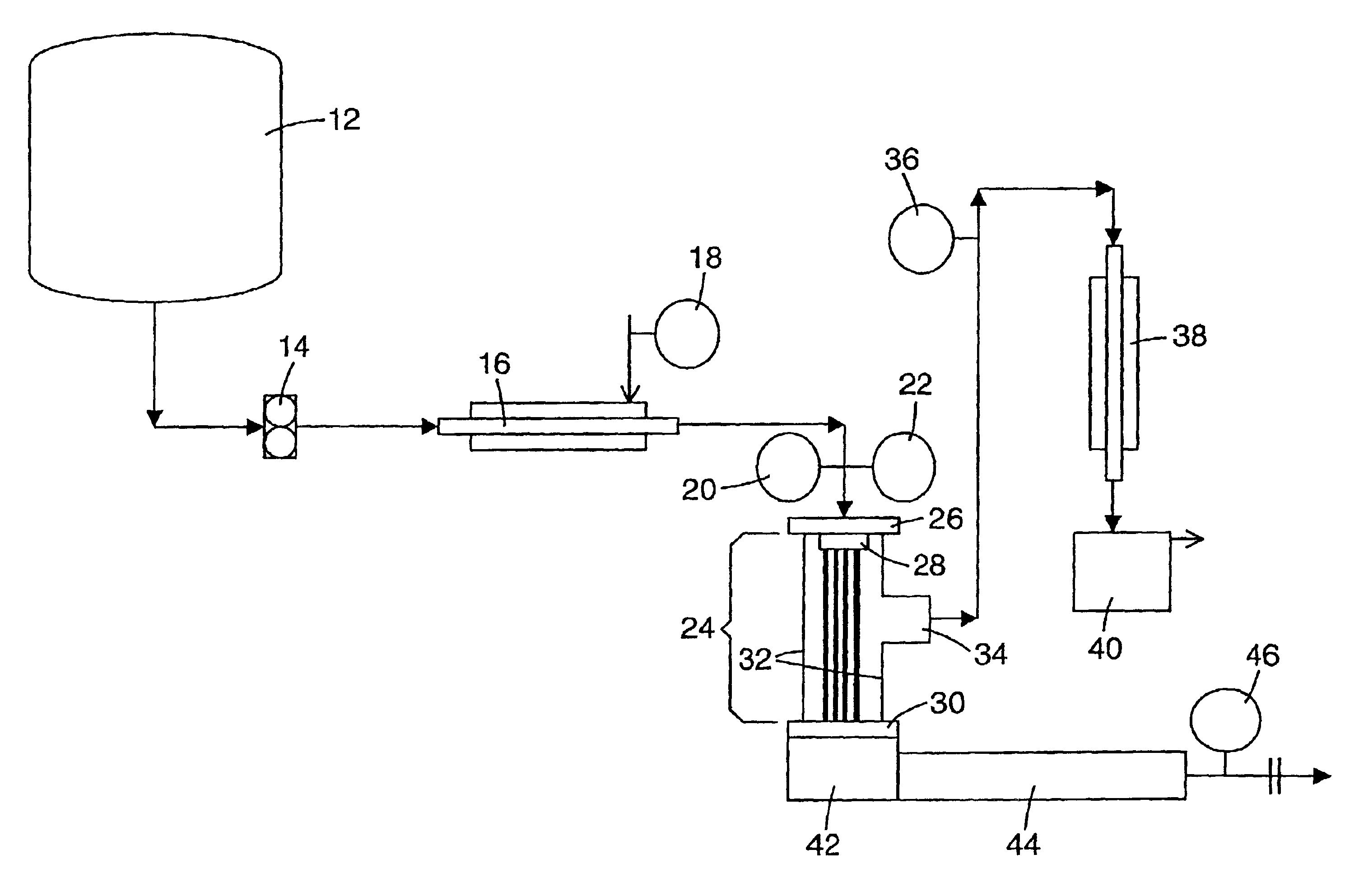
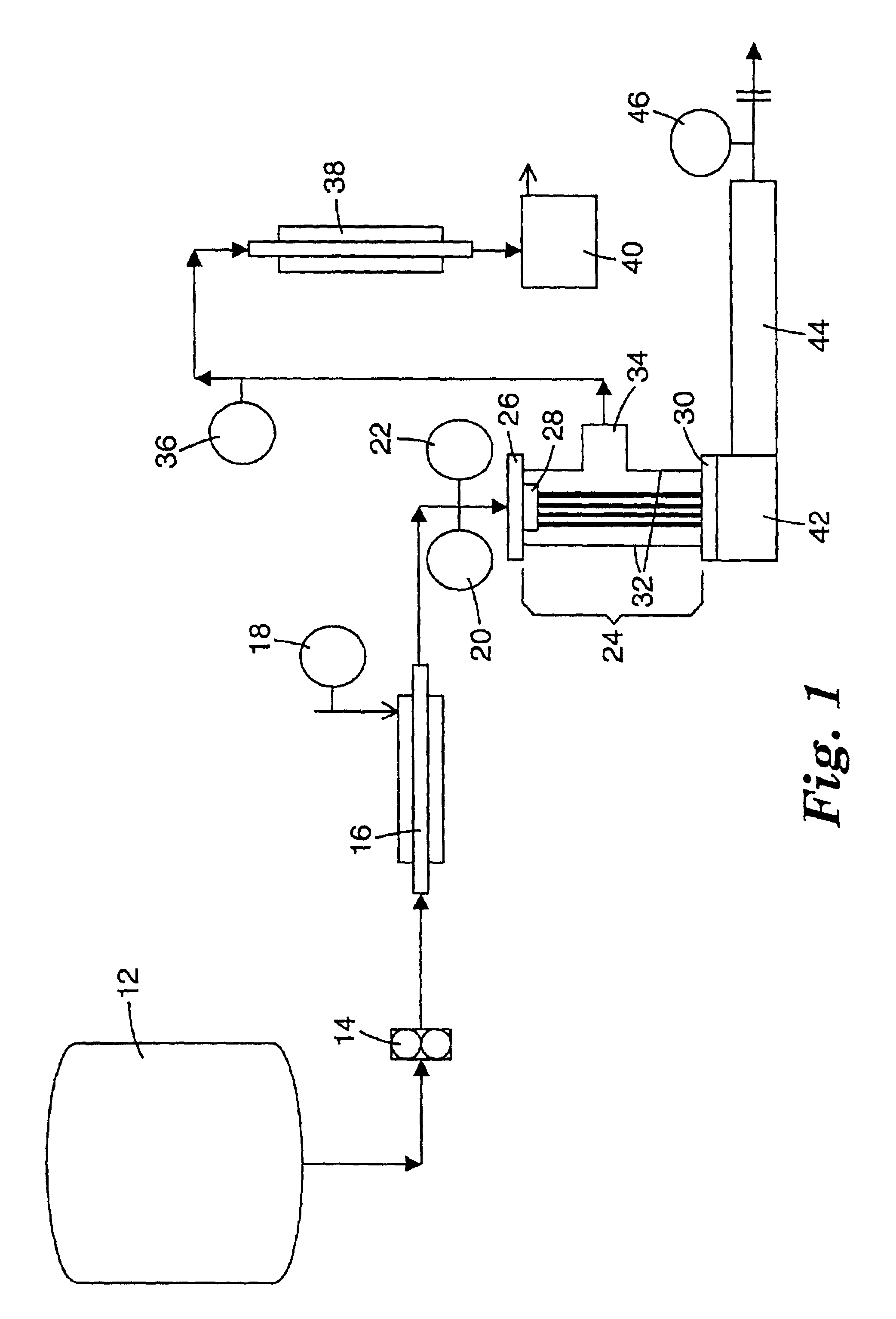
A ceramic colloid was prepared by addition of 163 g of boehmite (DISPERSAL™ 20 from Sasol GmbH, Hamburg, Germany) to a solution of 7.2 g of 70% nitric acid in 336 g of deionized water, followed by addition of 75 g methanol. This material was then processed according to Process A. The material was continuously fed through the heat exchanger (but with no heating), through the die and into the evaporation zone at one set of conditions. The product was then removed from the collection vessel. The pressure in the evaporation zone was then readjusted to produce products of different concentrations. For each set of conditions, samples of product were taken and analyzed for percent dried solids. The results are shown in Table 1.

TABLE 1InletEvaporationOutlet Concen-ConcentrationFeedZonetration (%(% DriedTemperaturePressureDried SolidsSampleSolids by wt.)(C.)(kPa)by wt.)128.23232.829.51228.23232.829.09328.23215.228.43428.23225.328.30528.23228.028.26

As seen, the outp...

example 2

Food Hydrocolloid

A food colloid was prepared by mixing 25.8 g corn starch (ARGO CORN STARCH™ from Best Foods, Englewood Cliffs, N.J.), 42.8 g granulated sugar (CRYSTAL SUGAR GRANULATED SUGAR™ from United Sugars Corp., Minneapolis, Minn.), and 435.8 g distilled water. This mixture was heated at atmospheric pressure with constant stirring to 95° C. to cause it to begin to increase in viscosity. The material was then cooled to room temperature. This material then processed according to Process A. The material was continuously fed through the heat exchanger, through the die and into the evaporation zone at one set of conditions of temperature and pressure. The product was then removed from the collection zone or vessel. The temperature in the heating zone and the pressure in the evaporation zone were then readjusted to produce products of different concentrations. For each set of conditions, samples of product were taken and analyzed for percent dried solids. The result are shown in Tab...

example 3

Organic-Inorganic Hydrocolloid

A colloid was prepared by mixing 50.1 g corn starch (ARGO CORN STARCH™), 225.4 g baking soda (ARM & HAMMER PURE BAKING SODA™ from Arm and Hammer Div. of Church & Dwight Co., Princeton, N.J.), and 224.7 g distilled water. This mixture was heated at atmospheric pressure with constant stirring to 70° C. to cause it to begin to bubble vigorously. The material was then cooled to 60° C. and stirred until the viscosity began to increase. The material was then cooled to room temperature. This material was then processed according to Process A. The material was continuously fed through the heat exchanger, through the die and into the evaporation zone at one set of conditions of temperature and pressure. The product was then removed from the collection zone. The temperature in the heating zone and the pressure in the evaporation zone were then readjusted to produce products of different concentrations. For each set of conditions, samples of product were taken and...


PUM


Abstract

A process for evaporating a portion of a colloidal solution, said process including: a) passing a colloidal solution, said colloidal solution including particles in a liquid medium, wherein at least a portion of said liquid medium includes at least one volatile component, through one or more orifices into an evaporation zone that has at least one inner surface, wherein said colloidal solution does not substantially contact said at least one inner surface of said evaporation zone as said colloidal solution is passed through said evaporation zone; b) applying pressure in said evaporation zone that is lower than the vapor pressure of said colloidal solution as it is passed into said evaporation zone, allowing for flash evaporation of at least a portion of said at least one volatile component from said colloidal solution; c) adjusting the pressure in said evaporation zone to evaporate an amount of said at least one volatile component from said colloidal solution; and d) collecting the remaining colloidal solution from said evaporation zone.

Description

FIELD OF THE INVENTIONThe present invention relates to the concentration of colloidal solutions. In particular, the present invention is a method for evaporating a desired portion of a colloidal solution.BACKGROUND OF THE INVENTIONColloidal solutions are between a true solution and a suspension. They are a dispersion of particles in a liquid medium where the size of the particles (or “colloids”) is between about 1 and about 1000 nanometers. They include, but are not limited to, sols, and aqua-sols or hydrosols of metal oxides (or precursors thereof). Sols, in particular, are colloidal solutions containing particles between about 1 and about 100 nanometers in size.Often when a colloidal solution is prepared, it is present in a relatively dilute concentration for ease in handling. Subsequent processing techniques to which the colloidal solution may eventually be subjected, however, may necessitate that the colloidal solution be concentrated.Current methods of concentrating colloidal s...

Claims


Application Information

Patent Timeline
IPC IPC(8): B01D3/00B01D3/42B01D3/06B01D1/00B01J13/00
CPCB01D3/06B01D3/42Y10S159/08
Inventor DAVIDSON, ROBERT S.ANDERSON, DANNY B.GERTH, RICHARD A.HOLM, DAVID R.
Owner 3M INNOVATIVE PROPERTIES CO
Why Eureka
Try Eureka