Hollow graphene sheet structure, electrode structure, process for the production thereof, and device thus produced

a graphene sheet and graphene sheet technology, applied in the manufacture of electrode systems, discharge tube main electrodes, electric discharge tubes/lamps, etc., can solve the problem that carbon nanotubes cannot be shaped by particulate gold

Inactive Publication Date: 2005-03-22
FUJIFILM BUSINESS INNOVATION CORP
View PDF3 Cites 62 Cited by
  • Summary
  • Abstract
  • Description
  • Claims
  • Application Information

AI Technical Summary

Benefits of technology

[0049]However, the inventors found that using the particulate gold fixed on the substrate makes it possible to partially decompose the carbon nanotube and hence cut the carbon nanotube at the heating step for oxidation if the particulate gold is prevented from moving freely.
[0051]In other words, the inventors found that the action of a particulate catalyst inducing oxidation of carbon nanotube makes it possible to shape carbon nanotube. The utilization of this action makes it also possible to provide a novel carbon nanotube, an electrode structure having a minute gap, etc.

Problems solved by technology

Thus, the carbon nanotube cannot be shaped by a particulate gold.

Method used


Image

  • Hollow graphene sheet structure, electrode structure, process for the production thereof, and device thus produced
  • Hollow graphene sheet structure, electrode structure, process for the production thereof, and device thus produced
  • Hollow graphene sheet structure, electrode structure, process for the production thereof, and device thus produced

Examples


1st embodiment

[0072]In the present embodiment, a carbon nanotube structure (a hollow graphene sheet structure) having at least one pair of hollow graphene sheets (carbon nanotube) disposed in a continuous form, in which adjacent ends of the pair of hollow graphene sheets are opposed to each other with a gap and a process for the production thereof will be described.

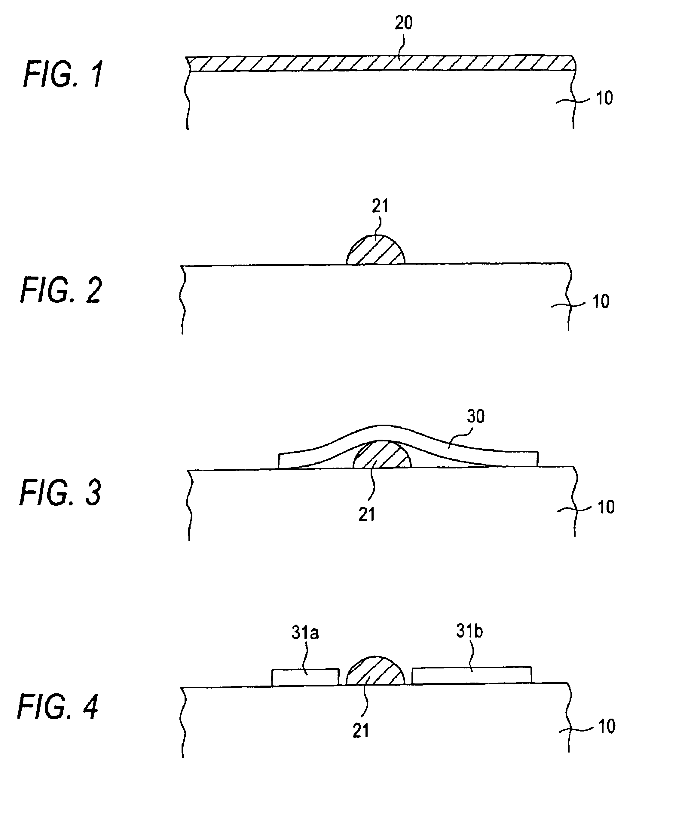
[0073]FIGS. 1 to 4 each are an enlarged sectional view schematically illustrating the process for the production of the carbon nanotube structure according to the present embodiment. FIG. 1 illustrates how a thin metal film 20 is formed on the surface of a substrate 10, FIG. 2 illustrates a particulate metal 21 which is formed by the thin metal film 20, FIG. 3 illustrates how the particulate metal 21 is covered by a carbon nanotube 30, and FIG. 4 illustrates a carbon nanotube structure obtained by cutting the carbon nanotube 30.

[0074]Firstly, as shown in FIG. 1, sputtering is made on the surface of the substrate to form the thin metal ...

2nd embodiment

[0107]In the first embodiment, the substrate 10 having a thin metal film 20 formed thereon is subjected to heating as pretreatment so that the metal is globurized. However, depending on the kind of the metal used or the substrate 10 to be combined therewith, the particulate metals 21 move little along the surface of the substrates 10 at a temperature close to the combustion temperature of the carbon nanotube at which catalytic action occurs. For example, when the diameter of the particulate metal 21 increases drastically under the conditions that the thin metal film 20 is formed, the particulate material 21 cannot move even at the temperature where the carbon nanotube 30 is oxidized by the action of the catalyst. In the case where a substrate 10 which can easily trap the metal atoms is used, the particulate metal 21 cannot escape from the trap at around the temperature where the carbon nanotube 30 is oxidized.

[0108]Thus, in the case where an immobile metal is used as particulate met...

3rd embodiment

[0123]A novel carbon nanotube structure obtained by reducing the thickness of a continuous carbon nanotube at a longitudinally middle point unlike the 1st and 2nd embodiments and a process for the production thereof will be described hereinafter.

[0124]The carbon nanotube structure obtained by the production process is a hollow graphene sheet structure having a graphene sheet having at least one layer and tube shape and a region in a longitudinal direction in which another graphene sheet having at least one layer is laminated on the graphen sheet.

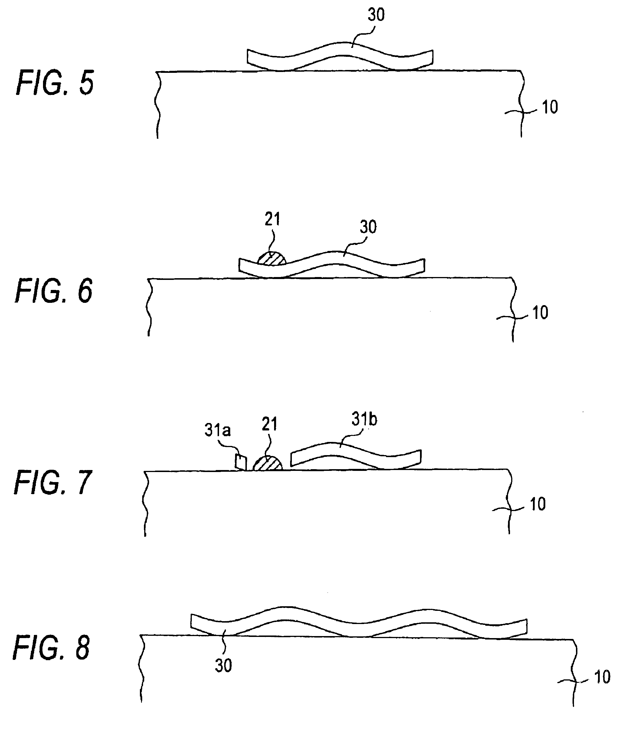
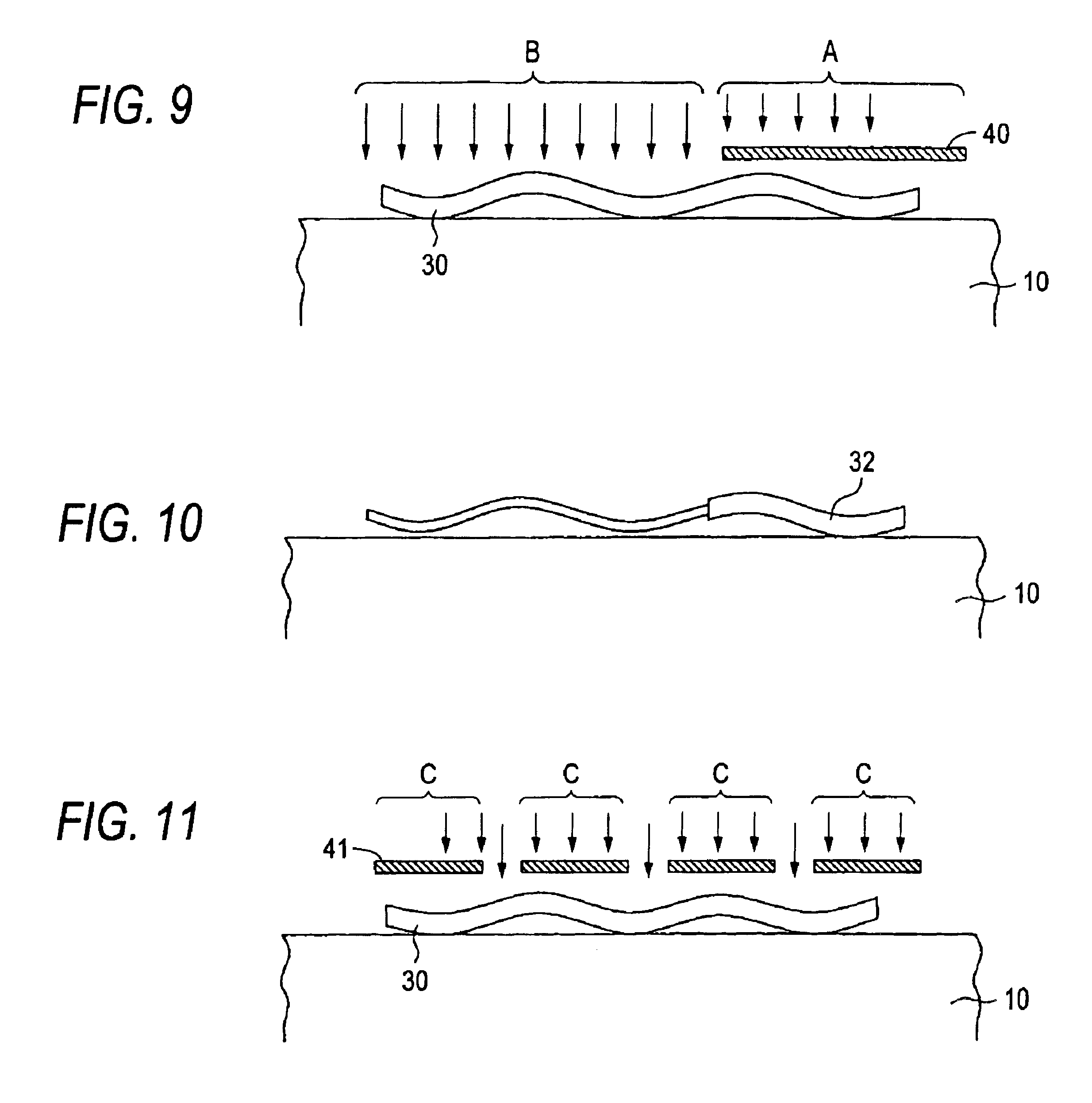
[0125]FIGS. 8 to 11 each are an enlarged sectional view schematically illustrating the process for the production of a carbon nanotube structure according to the present embodiment. FIG. 8 illustrates how the carbon nanotube 30 is disposed on the surface of the substrate 10, FIG. 9 illustrates how a metal is vacuum-evaporated onto the carbon nanotube30 with a mask 40, FIG. 10 illustrates a carbon nanotube structure which is reduced in thickn...


PUM

PropertyMeasurementUnit
diameteraaaaaaaaaa
thicknessaaaaaaaaaa
particle diameteraaaaaaaaaa

Abstract

A hollow graphene sheet structure has at least one pair of hollow graphene sheet materials disposed in a continuous form, in which the adjacent ends of the pair of hollow graphene sheet materials are opposed to each other with a gap.

Description

BACKGROUND OF THE INVENTION[0002]1. Field of the Invention[0003]The present invention relates to a hollow graphene sheet structure and an electrode structure which can be widely used in electronic devices, etc., a process for the production thereof and a novel device comprising the electrode structure.[0004]2. Description of the Related Art[0005]A carbon nanotube comprises a graphene sheet (sheet-like structure of hexagonal network of carbon atoms) rounded in a hollow form. Since a carbon nanotube shows a high electrical conductivity despite its diameter as small as 1 to 50 nm in addition to its chemical stability, it has been under extensive study for its application to devices ranging from macroscale device such as discharge electrode to nanoscale electronic device. Since a carbon nanotube itself is tough besides being electrically conductive, it has been under study for application to support for reinforcing material or structure and hydrogen storing material utilizing the action...

Claims


Application Information

Patent Timeline
Patent Type & Authority Patents(United States)
IPC IPC(8): H01J1/30H01J9/02H01J1/304B82B1/00B82B3/00C01B31/02H01L29/06H01L49/00
CPCB82Y10/00H01J9/025H01J1/304H01J2201/30469
Inventor KISHI, KENTAROYOSHIZAWA, HISAEWATANABE, HIROYUKIHASEGAWA, SHINJIYAMADA, HIROKAZUWATANABE, MIHO
Owner FUJIFILM BUSINESS INNOVATION CORP
Why Eureka
Try Eureka