Optical material, optical element, multilayer diffraction optical element, optical system, and method of molding optical element

a technology of optical elements and optical elements, applied in the field of optical elements, optical elements, multilayer diffraction optical elements, optical systems, etc., can solve the problems of small load, industrially difficult, and inability to fully correct chromatic aberration, etc., and achieve the effect of greater refractive index dispersion

Inactive Publication Date: 2005-03-22
CANON KK
View PDF19 Cites 11 Cited by
  • Summary
  • Abstract
  • Description
  • Claims
  • Application Information

AI Technical Summary

Benefits of technology

[0018]It is an object of the present invention to provide an optical material having greater refractive index dispersion capable of suppressing crystallization of the optical material during molding at room temperature and appropriately controlling a dropping am

Problems solved by technology

When the lens configuration or the number of lenses is restricted or glass materials to be used are limited, there has been a case where chromatic aberration cannot fully be corrected.
Since polyvinylcarbazole is a very fragile material, a small load can easily crack it, for example.
This is industrially very difficult.
In recent years, diffraction gratings become finely and complexly shaped, making such method much more difficult.
Although diffraction optical elements and the like can be molded into any shapes by applying light polymerization, N-vinylcarbazole is crystallized at room temperature and cannot directly be used for replica molding that is usually performed at room temperature.
However, molds for the replica molding are generally restricted.
Accordingly, the mold and the optical eleme

Method used


Image

  • Optical material, optical element, multilayer diffraction optical element, optical system, and method of molding optical element
  • Optical material, optical element, multilayer diffraction optical element, optical system, and method of molding optical element
  • Optical material, optical element, multilayer diffraction optical element, optical system, and method of molding optical element

Examples


example 1

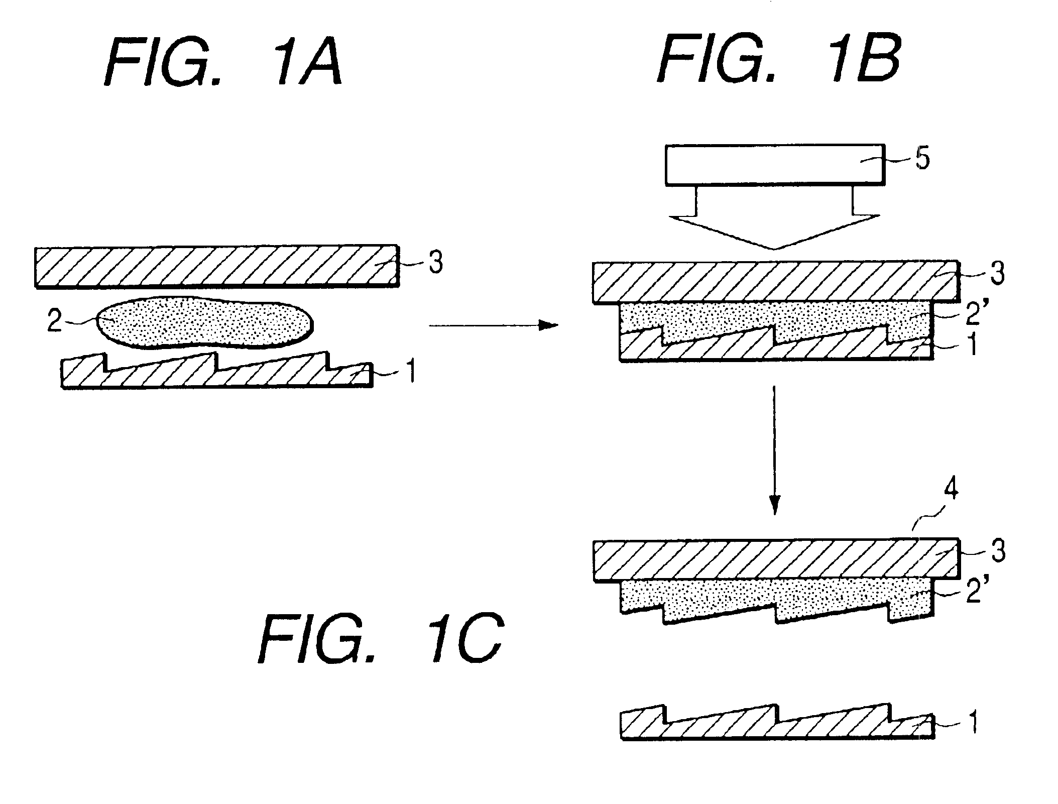
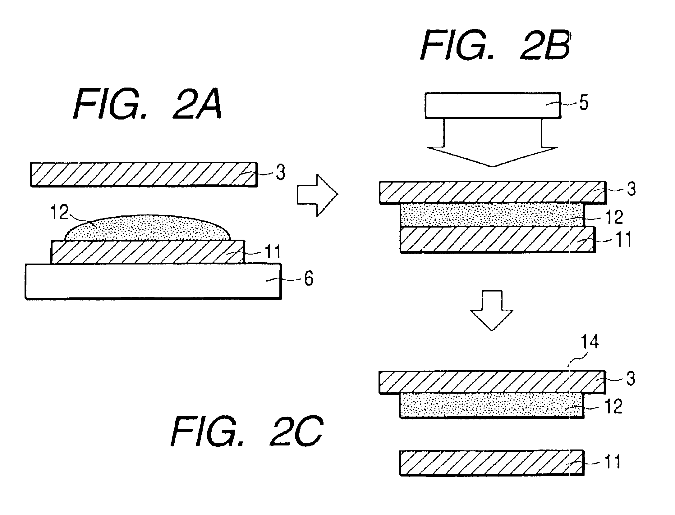
[0050]In example 1, were blended 7.9 g of N-vinylcarbazole (manufactured by TOKYO KASEI KOGYO), 1.0 g of polyvinylcarbazole (manufactured by Acros), and 0.1 g of Irgacure 184 (manufactured by Ciba Specialty Chemicals) as a light polymerization initiator. The blend was heated and melted at 80° C. for two hours, and then fully stirred to obtain a photo-curing resin 12. FIGS. 2A to 2C show a method of molding an optical element in example 1. The mutually corresponding parts in FIGS. 2A to 2C and FIGS. 1A to 1C are designated by the same reference numerals. FIGS. 2A to 2C differ from FIGS. 1A to 1C in that a flat mold 11 is used to facilitate the experiment instead of the mold 1 processed into a diffraction grating shape. Consequently, no grating is formed on the molded photo-curing resin. At this time, the viscosity of the photo-curing resin 12 was 71.8 mPa·s (80° C.).

[0051]Then, a dispenser was used to discharge approximately 0.04 g of the photo-curing resin 12 kept at 80° C. onto the...

example 2

[0060]In example 2, experiments (experiment examples 5 to 9) were conducted by blending N-vinylcarbazole (manufactured by TOKYO KASEI KOGYO), polyvinylcarbazole (manufactured by Acros), and Irgacure 184 (manufactured by Ciba Specialty Chemicals) as a light polymerization initiator at ratios as shown in Table 2. The experiment method is completely the same as for example 1. The mixture was heated and melted at 80° C. for two hours, and then fully stirred to prepare each optical material for this example. For a comparison purpose, we also conducted comparison experiment example 5 based on a blend ratio as shown in Table 2. Table 3 lists viscosities of the optical materials for examples 5 through 9 and the comparison experiment example.

TABLE 2Weight (g) of N-Weight (g) ofWeight (g) ofvinylcarbazolepolyvinylcarbazoleIrgacure 184Comparison9.90.00.1experimentexample 5Experiment8.91.00.1example 5Experiment7.92.00.1example 6Experiment6.93.00.1example 7Experiment5.94.00.1example 8Experiment4...

example 3

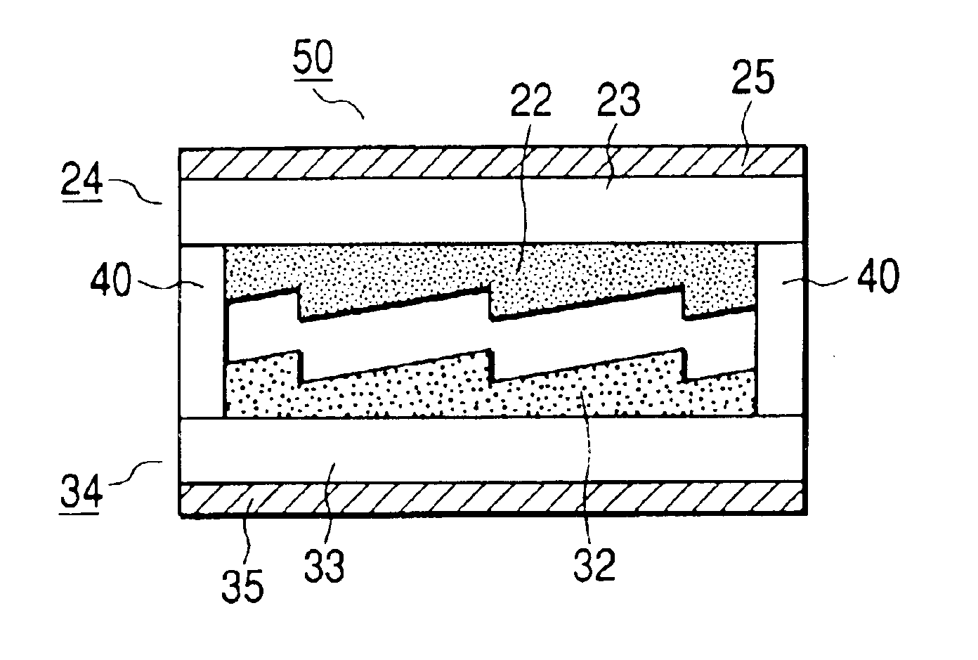
[0070]In example 3, 7.9 g of N-vinylcarbazole (manufactured by TOKYO KASEI KOGYO), 1.0 g of polyvinylcarbazole (manufactured by Acros), and 0.1 g of Irgacure 184 (manufactured by Ciba Specialty Chemicals) as a light polymerization initiator ware blended. The blend was heated and melted at 80° C. for two hours, and then fully stirred to obtain an optical material 22. Then, a dispenser was used to discharge approximately 0.04 g of the optical material 22 kept at 80° C. onto the mold kept at room temperature. The mold temperature is controlled so as to be within ±1.0° C. Since no crystallization occurred, the lens blank 23 kept at room temperature was gently placed on the optical material. Then, the lens blank 23 was gently pressed to spread the optical material 22 to fill it between the lens blank 23 and the mold. Further, ultraviolet light with the center wavelength 365 nm was applied for 300 seconds at 40 mW from the direction of the glass plate to cure the optical material 22. Fina...


PUM

PropertyMeasurementUnit
Ratioaaaaaaaaaa
Shapeaaaaaaaaaa

Abstract

An optical element having a diffraction shape uses an optical material comprising at least N-vinylcarbazole, polyvinylcarbazole, and the light polymerization initiator. By using such optical material, it is possible to suppress crystallization of the optical material during molding even at room temperature and appropriately control the dropping amount suited for replica molding. It is possible to provide the optical material also suited for replica molding at room temperature by setting a ratio of N-vinylcarbazole to polyvinylcarbazole, i.e. N-vinylcarbazole/polyvinylcarbazole, to a range between 90/10 and 70/30.

Description

BACKGROUND OF THE INVENTION[0002]1. Field of the Invention[0003]The present invention relates to an optical material used for optical elements such as a lens, a filter, a mirror, and a refraction optical element, and more particularly to an optical material with large refractive index dispersion. Further, the present invention relates to an optical element formed by the optical material and a method of forming the optical element.[0004]2. Related Background Art[0005]Conventionally, an optical system comprising a plurality of lenses for refracting a light beam decreases chromatic aberration by combining glass materials with different dispersion characteristics. Objective lenses of a telescope, for example, comprise a positive lens using a small-dispersion glass material and a negative lens using a large-dispersion glass material. These lenses are combined to correct chromatic aberration appearing on an axis. When the lens configuration or the number of lenses is restricted or glass m...

Claims


Application Information

Patent Timeline
IPC IPC(8): C08L51/00C08F271/00C08F271/02G02B27/00G02B1/04G02B5/18G02B3/00G02B30/60
CPCC08F271/00C08F271/02C08L51/003G02B1/04G02B5/1823G02B5/1852G02B27/0037G02B27/4288G02B27/4211G02B27/4222G02B27/4277C08L51/06C08G73/06
Inventor OHGANE, MASANOBU
Owner CANON KK
Why Eureka
Try Eureka