Emissions control system for increasing selective catalytic reduction efficiency

a technology of selective catalytic reduction and emission control system, which is applied in the direction of engine starters, electric control, muscle operated starters, etc., can solve the problems of system clogging or plugging, the minimum hydrolysis temperature of the urea solution to reduce the efficiency and the ineffectiveness of the scr catalyst system. achieve the effect of increasing the efficiency of the emissions control system and reducing the nox in the exhaust gas stream

Inactive Publication Date: 2005-03-29
CATERPILLAR INC
View PDF6 Cites 68 Cited by
  • Summary
  • Abstract
  • Description
  • Claims
  • Application Information

AI Technical Summary

Benefits of technology

Still another aspect of the invention provides a method for increasing the efficiency of an emissions control system for a compression ignition engine capable of producing an exhaust gas stream to be treated by a reduction agent which is mixed with the exhaust gas stream to convert the exhaust gas stream prior to being directed into an SCR catalyst capable of reducing NOx in the exhaust gas stream, the method providing the steps of determining the temperature of the exhaust gas stream prior to being mixed with the reduction agent; determining whether the temperature of the exhaust gas stream is at a predetermined temperature; and controlling the direction of flow of the exhaust gas stream based upon the temperature of the exhaust gas stream.

Problems solved by technology

Current and proposed regulations and legislation challenge manufacturers to achieve good fuel economy while at the same time require the reduction of the emissions of particulates and NOx.
Consequently, the SCR catalyst is not effective when the engine is operating under light load conditions.
When urea solution is used, another factor which reduces the effectiveness of the SCR catalyst system is the minimum hydrolysis temperature of the urea solution.
If the unhydrolyzed solution of urea is injected into the SCR catalyst, some of the urea is deposited on the surface of the SCR catalyst as a solid residue, which results in the system clogging or plugging.
These conditions occur when an engine is operated under transient conditions, or under light load conditions, and NOx reduction by the SCR catalyst can not be achieved.
A third factor that reduces the efficiency of an SCR catalyst system is that the surface temperature of the catalyst must be at a minimum temperature.
Until this temperature is obtained, the solution of urea should not be injected into the catalyst, and the delay in injecting the solution of urea causes the SCR catalyst system to lose efficiency.
One other factor that reduces the efficiency of the SCR catalyst system occurs when the engine is operating under a light load or an idle condition, and combustion takes place at low in-cylinder temperatures.
The residue formed can block the micro pores of the catalyst washcoat, causing the catalyst to reduce efficiency through loss of surface area within the catalyst.

Method used


Image

  • Emissions control system for increasing selective catalytic reduction efficiency
  • Emissions control system for increasing selective catalytic reduction efficiency
  • Emissions control system for increasing selective catalytic reduction efficiency

Examples


Embodiment Construction

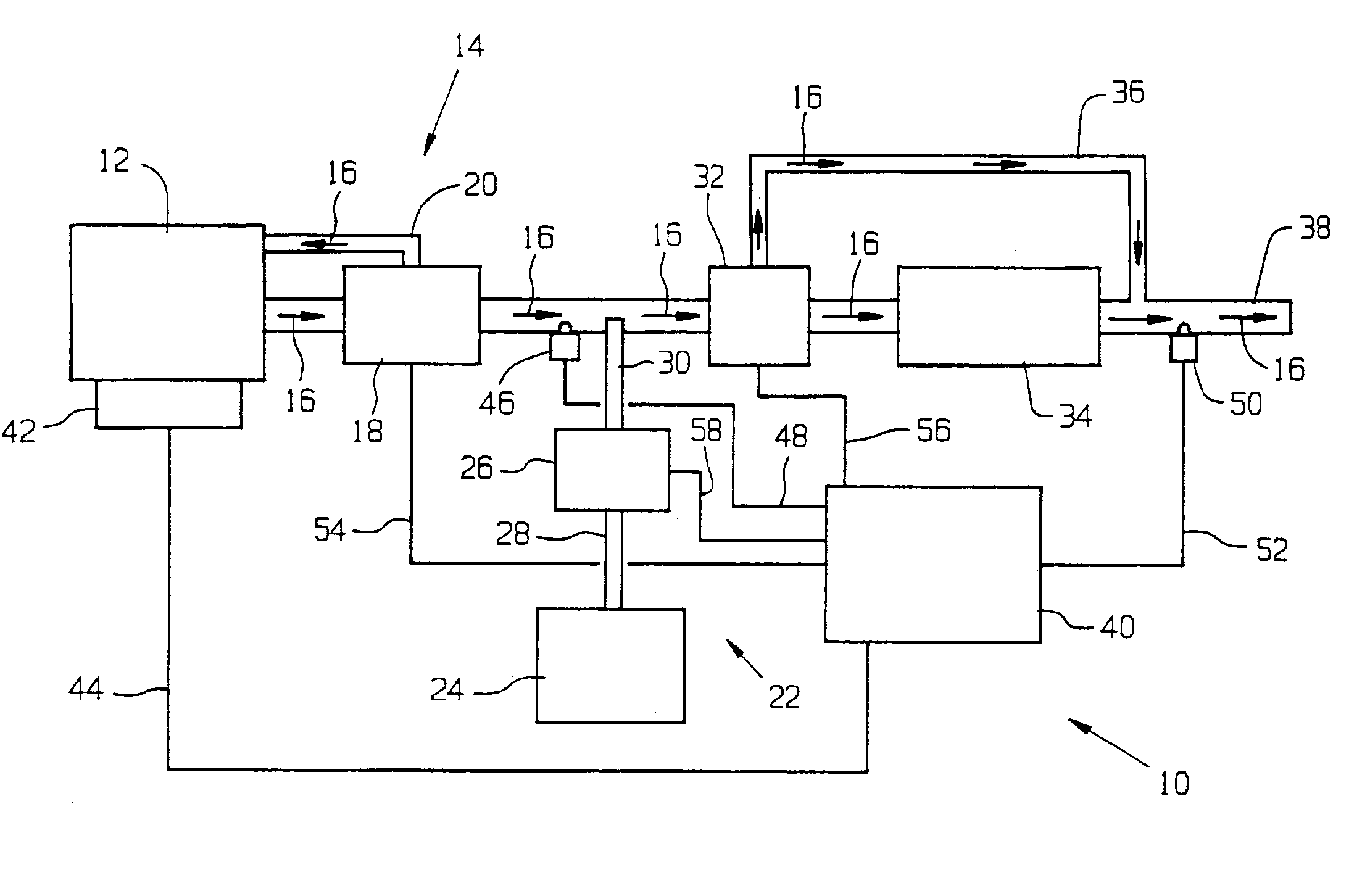
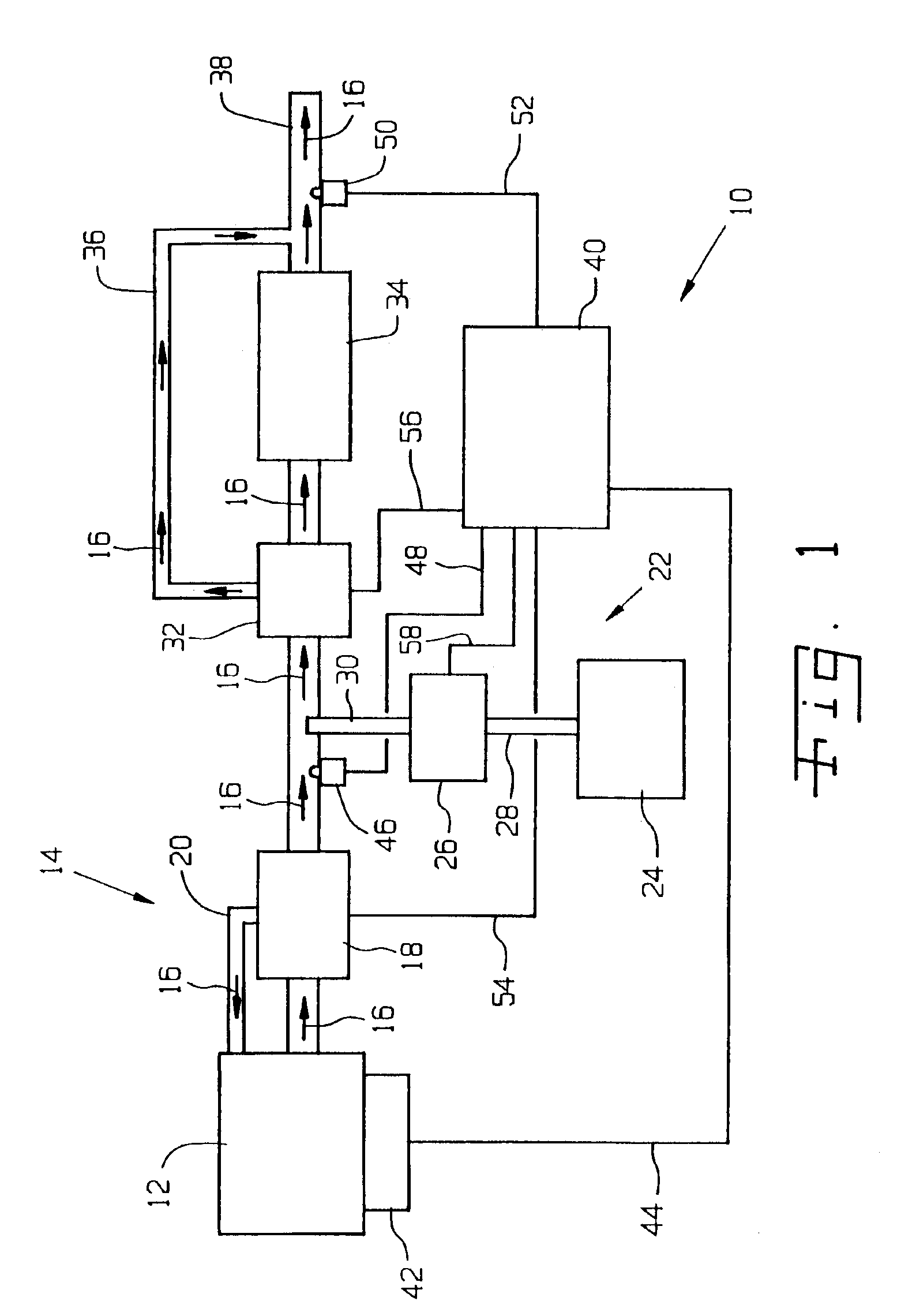
Referring now to the drawings, FIG. 1 illustrates an emissions control system 10 constructed according to the present invention. The emissions control system 10 is used to control the emissions from a compression ignition engine 12, such as a diesel engine. The engine 12 includes an exhaust system 14 in which an exhaust gas stream, indicated by arrows 16, is produced. The exhaust system 14 includes one or more exhaust gas recirculation (EGR) valves 18 which are capable of being metered in order to direct all, a portion, or none of the exhaust gas stream 16 back into the engine 12 through an intake manifold 20.

The exhaust gas stream 16 is provided toward an ammonia generator system 22 which is capable of injecting a reduction agent into the exhaust gas stream 16. The system 22 includes a storage tank 24 for storing a reactant such as urea solution. The urea solution is drawn out of the tank 24 by a pump 26 through a conduit 28. Although not shown, the tank 24 may include a fill port ...


PUM


Abstract

An emissions control system is used with a compression ignition engine capable of producing an exhaust gas stream to be treated by a reduction agent which is mixed with the exhaust gas stream to convert the exhaust gas stream prior to being directed into an SCR catalyst capable of reducing NOx in the exhaust gas stream. An exhaust gas recirculation valve is associated with the compression ignition engine for directing the exhaust gas stream back into the compression ignition engine. An electronic control unit and sensors determine whether the temperature of the exhaust gas stream is at a predetermined temperature, and if so control operation of the valve to allow a portion of the exhaust gas stream to be directed into the SCR catalyst. A bypass valve may also be provided to prevent the exhaust gas stream from entering into the SCR catalyst.

Description

TECHNICAL FIELDThe present invention relates generally to emissions control systems for electronically controlled compression ignition engines, and more particularly to an emissions control system for increasing selective catalytic reduction (SCR) efficiency of a compression ignition engine.BACKGROUNDCompression ignition engines, such as diesel engines, provide advantages in fuel economy, but produce and emit both NOx (nitrogen oxides) and particulates during normal operation. When primary measures (actions that affect the combustion process itself, e.g., exhaust gas recirculation and engine timing adjustments) are taken to reduce one, the other is usually increased. Thus, combustion conditions selected to reduce pollution from particulates and obtain good fuel economy tend to increase the output of NOx. Current and proposed regulations and legislation challenge manufacturers to achieve good fuel economy while at the same time require the reduction of the emissions of particulates a...

Claims


Application Information

Patent Timeline
Patent Type & Authority Patents(United States)
IPC IPC(8): F01N3/20F01N9/00
CPCF01N3/208F02D41/005F02D41/024F01N2410/06F01N2410/12F01N2560/026F01N2560/06F01N2610/146Y02T10/24F02D41/1446Y02T10/26Y02T10/47F01N2900/08Y02T10/12Y02T10/40
Inventor LIANG, CHO Y.MCCOY, STEVEN R.
Owner CATERPILLAR INC
Why Eureka
Try Eureka