
Sensor design and process

a technology of accelerometer and sensor, applied in the field of accelerometer, can solve the problems of inability to achieve a large dynamic range, adversely affect the quality of data acquired by the accelerometer, and suffer from a number of limitations, so as to prevent degradation of the performance of the accelerometer, reduce stiction, and reduce stiction

Inactive Publication Date: 2005-03-29
INPUT OUTPUT INC
View PDF22 Cites 29 Cited by
  • Summary
  • Abstract
  • Description
  • Claims
  • Application Information

AI Technical Summary

Benefits of technology

"The present invention provides an accelerometer that can reliably measure acceleration. The accelerometer is vacuum-sealed and includes a balanced metal pattern to prevent degradation of performance. The electrical leads of the accelerometer are isolated using a dicing process. The accelerometer also includes overshock protection bumpers and patterned metal electrodes to reduce stiction during operation. The technical effects of the invention include improved accuracy and reliability of acceleration measurements, as well as reduced stiction and improved performance of the accelerometer."

Problems solved by technology

In particular, accelerometers are often used in seismic applications to gather seismic data Existing accelerometers suffer from a number of limitations.
These limitations include bowing of cap wafers due to thermal induced stress and an inability to achieve a large dynamic range due to the effects of Brownian noise, both of which adversely affect the quality of data acquired by these accelerometers.
Many existing accelerometers fail to provide a large dynamic range, sub micro-G level sensitivity, high shock withstanding, and good cross-axis rejection in a cost-effective technology.

Method used


Image

  • Sensor design and process
  • Sensor design and process
  • Sensor design and process

Examples


Embodiment Construction

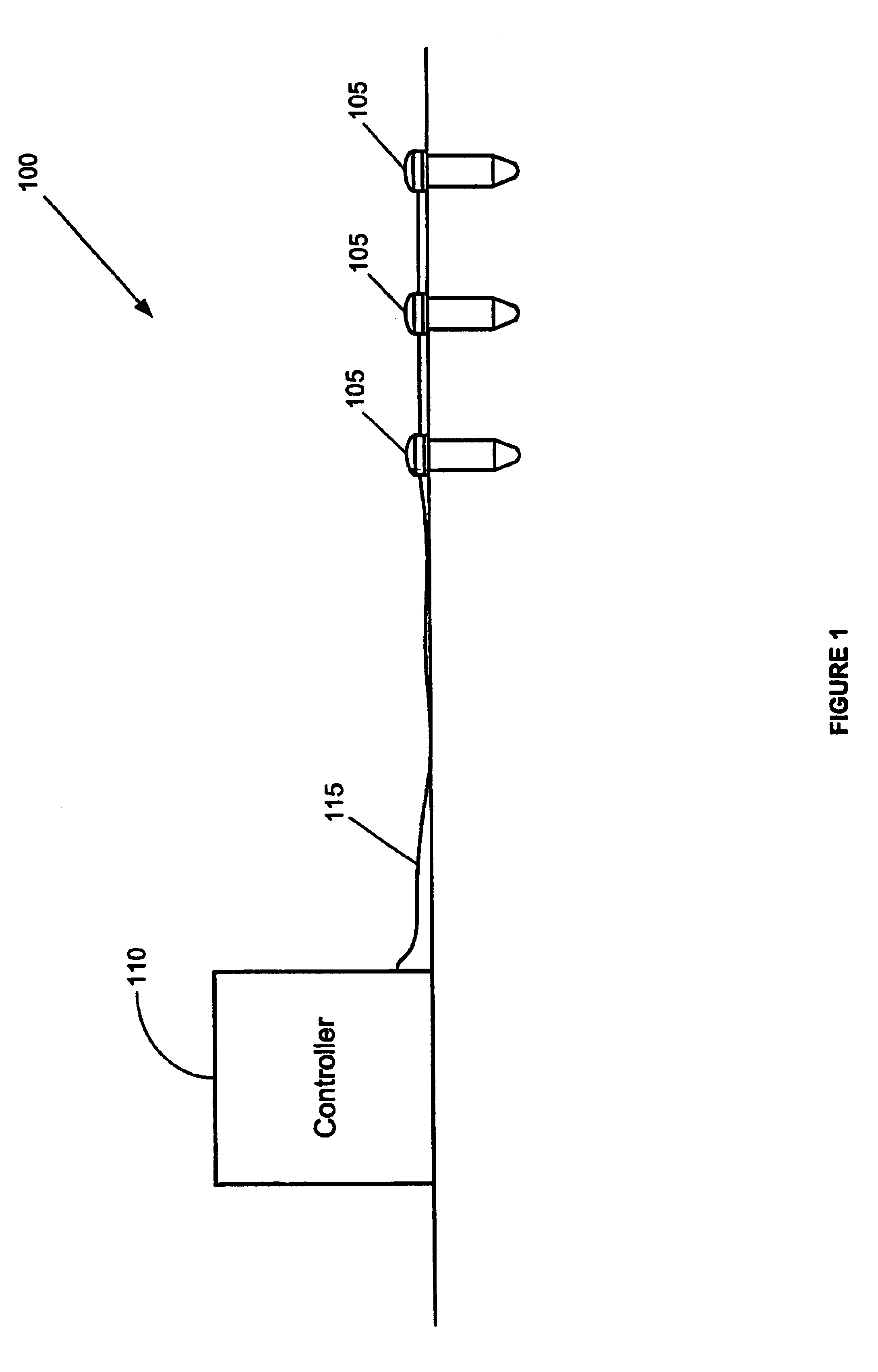
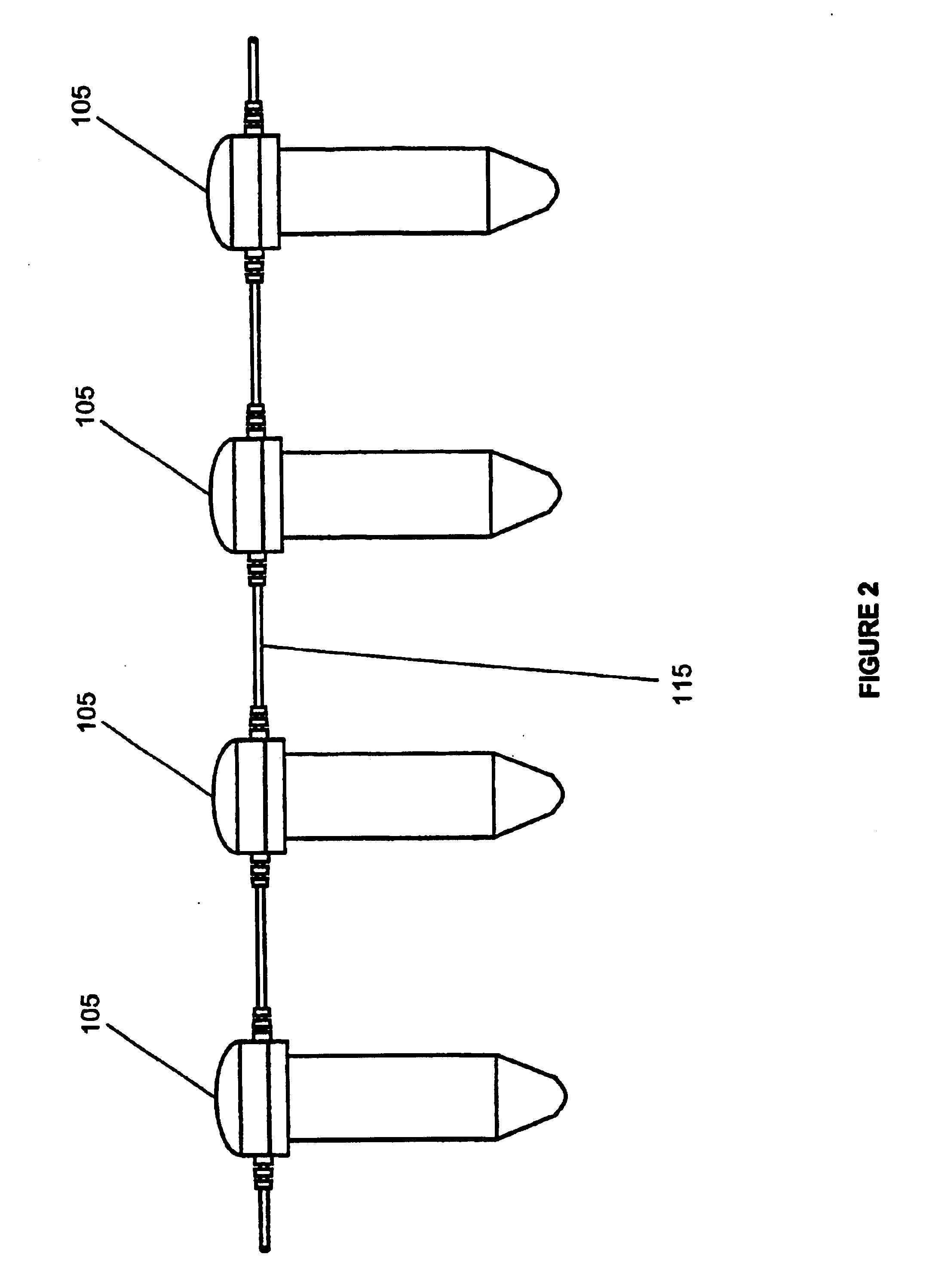
Referring initially to FIG. 1, a preferred embodiment of a system 100 designed to record data measurements is illustrated. The system 100 preferably includes one or more sensors 105, a controller 110, and cabling 115.

Within the system 100, the sensors 105 are used to detect data measurements. In a preferred embodiment, the system 100 is used in seismic applications to record seismic data measurements. The sensors 105 may be any number of conventional commercially available sensors, such as, for example, a geophone, a hydrophone, or an accelerometer. In a preferred embodiment, each of the sensors 105 is an accelerometer.

The controller 110 is used to monitor and control the sensors 105. The controller 110 is preferably coupled to the sensors 105 by the cabling 115. The controller 110 may be any number of conventional commercially available controllers suitable for controlling the sensors 105, such as, for example, a seismic data acquisition device, a PID controller, or a microcontroll...


PUM

PropertyMeasurementUnit
depthaaaaaaaaaa
depthaaaaaaaaaa
heightaaaaaaaaaa

Abstract

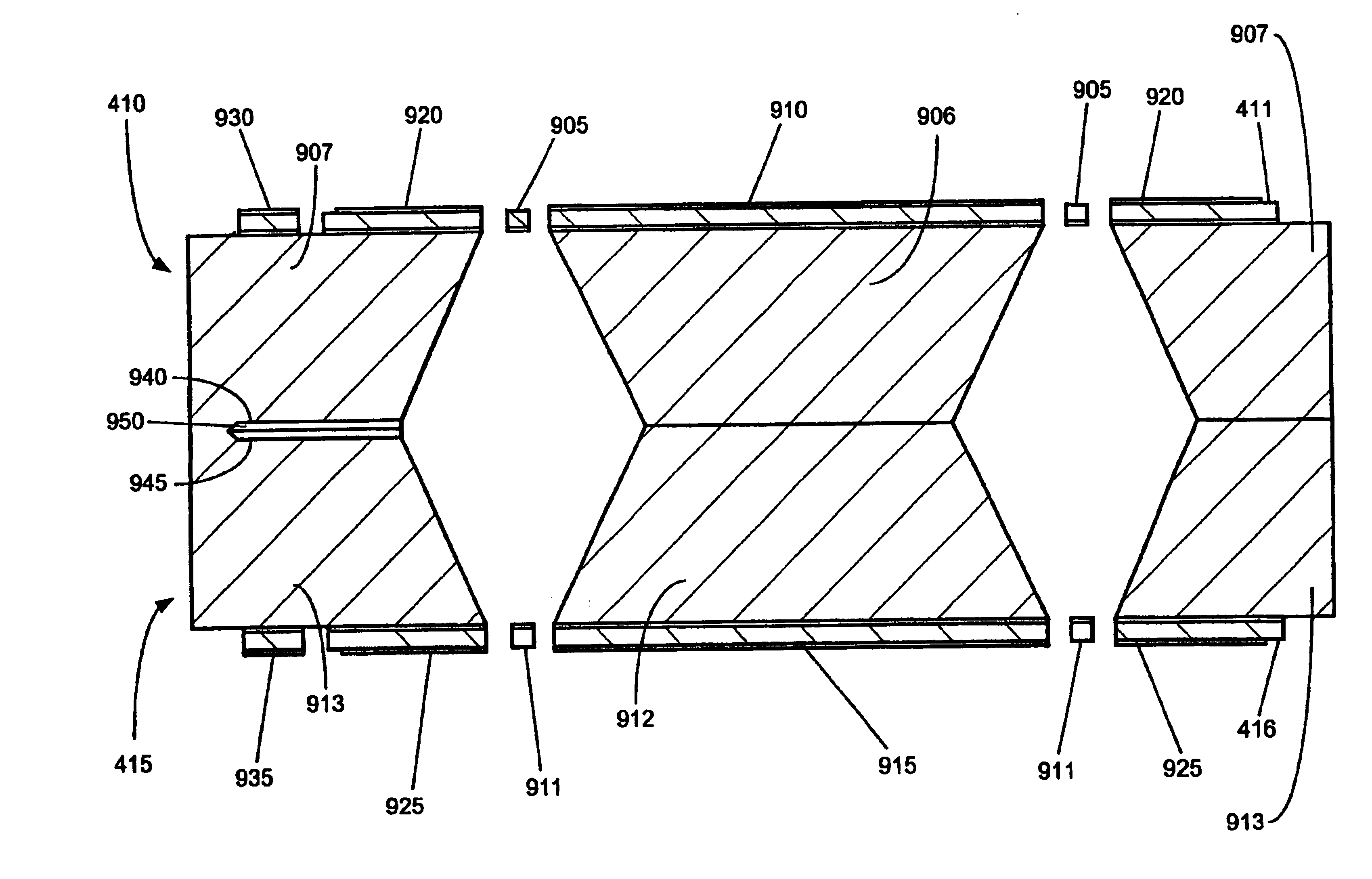
An accelerometer (305) for measuring seismic data. The accelerometer (305) includes an integrated vent hole for use during a vacuum sealing process and a balanced metal pattern for reducing cap wafer bowing. The accelerometer (305) also includes a top cap press frame recess (405) and a bottom cap press frame recess (420) for isolating bonding pressures to specified regions of the accelerometer (305). The accelerometer (305) is vacuum-sealed and includes a balanced metal pattern (730) to prevent degradation of the performance of the accelerometer (305). A dicing process is performed on the accelerometer (305) to isolate the electrical leads of the accelerometer (305). The accelerometer (305) further includes overshock protection bumpers (720) and patterned metal electrodes to reduce stiction during the operation of the accelerometer (305).

Description

BACKGROUND OF THE INVENTIONThis invention relates generally to an accelerometer and more particularly to a method of fabricating an accelerometer that reduces bowing of wafer bodies and facilitates the creation of a low-pressure environment within the accelerometer.Accelerometers are used to detect and record environmental data. In particular, accelerometers are often used in seismic applications to gather seismic data Existing accelerometers suffer from a number of limitations. These limitations include bowing of cap wafers due to thermal induced stress and an inability to achieve a large dynamic range due to the effects of Brownian noise, both of which adversely affect the quality of data acquired by these accelerometers. Many existing accelerometers fail to provide a large dynamic range, sub micro-G level sensitivity, high shock withstanding, and good cross-axis rejection in a cost-effective technology.The present invention is directed to overcoming one or more of the limitations...

Claims


Application Information

Patent Timeline
Patent Type & Authority Patents(United States)
IPC IPC(8): G01D11/24G01V1/18G01V1/02G01V1/16G01V1/047G01V1/053G01V1/38G01V1/104G01P1/02G01P15/02G01P15/08G01P15/125H01L21/465
CPCG01D11/245G01P1/023G01P15/08G01P15/125G01V1/053G01V1/104G01V1/181G01V1/38G01V1/047Y10T29/49007
Inventor SELVAKUMAR, ARJUNGOLDBERG, HOWARD D.YU, DULIIP, MATTHEWSCHMIDT, MARTIN A.MARSH, JAMES L.FUNG, BING-FAISIMON, PHILIP
Owner INPUT OUTPUT INC
Learn More