
Fuel delivery rail assembly

a technology of fuel delivery rails and assembly lines, which is applied in the direction of liquid fuel feeders, machine/engines, fuel injecting pumps, etc., to achieve the effects of reducing vibration, reducing pressure fluctuations within fuel passages, and eliminating the emission of uncomfortable high-frequency nois

Inactive Publication Date: 2005-03-29
USUI KOKUSAI SANGYO KAISHA LTD
View PDF10 Cites 23 Cited by
  • Summary
  • Abstract
  • Description
  • Claims
  • Application Information

AI Technical Summary

Benefits of technology

It is an object of the present invention to provide a fuel delivery rail assembly which can reduce the pressure fluctuations within the fuel passages caused by fuel injections, and also to reduce the vibrations caused by fuel reflecting waves (shock waves), to thereby eliminate emission of uncomfortable high-frequency noise.
As a result of the above construction of the invention, in a fuel delivery rail assembly having a fuel conduit made by steel, stainless steel or press materials, it has been found that it becomes possible to eliminate emission of uncomfortable noise including high-frequency noise. These noise are caused by the vibration and pressure pulsations due to the reflecting waves of injections and lack of dampening performance of the conduit.
Further, the high-frequency noise suppressing means work to prevent the absorbing surface from vibrating freely and emitting high-frequency noise. Thus, a high-frequency sound component contained in the noise is minimized and diffusion of high-frequency noise is considerably eliminated.
In this invention, thickness of each wall of the conduit, ratio of the horizontal size to the vertical size, and the range of clearance between the fuel inlet of the socket and its confronting surface are preferably defined by experiments or calculations such that, especially during idling of the engine, the vibrations and pressure pulsations are minimized.

Problems solved by technology

These noise are caused by the vibration and pressure pulsations due to the reflecting waves of injections and lack of dampening performance of the conduit.

Method used


Image

  • Fuel delivery rail assembly
  • Fuel delivery rail assembly
  • Fuel delivery rail assembly

Examples


first embodiment

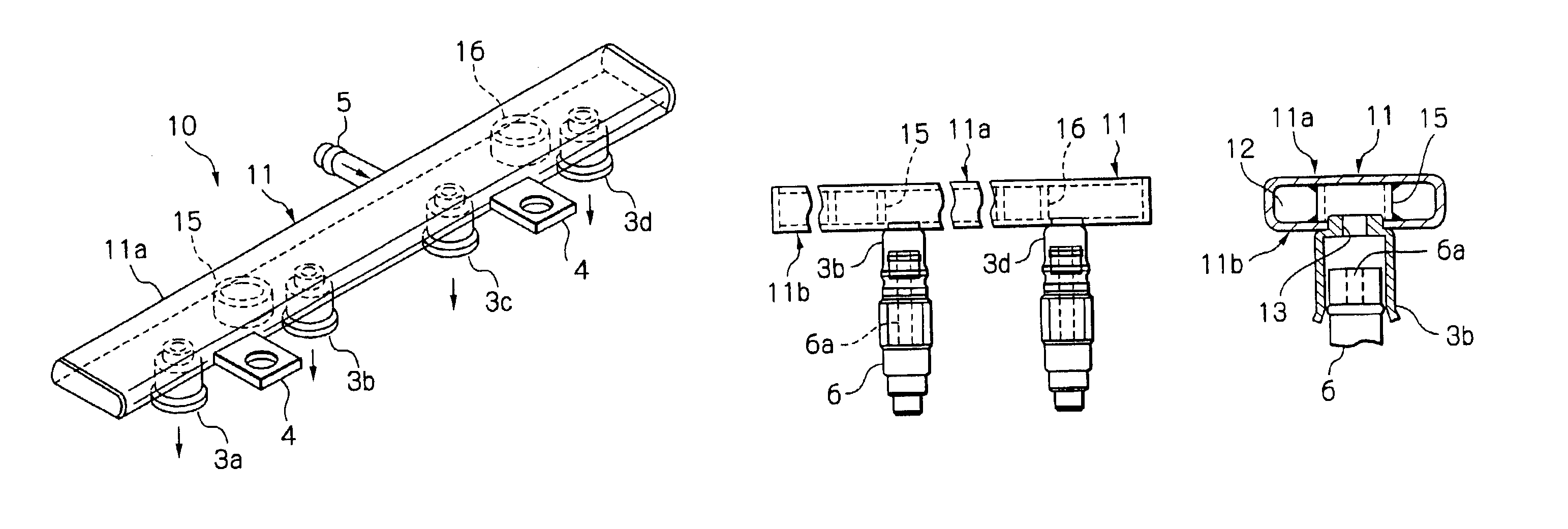
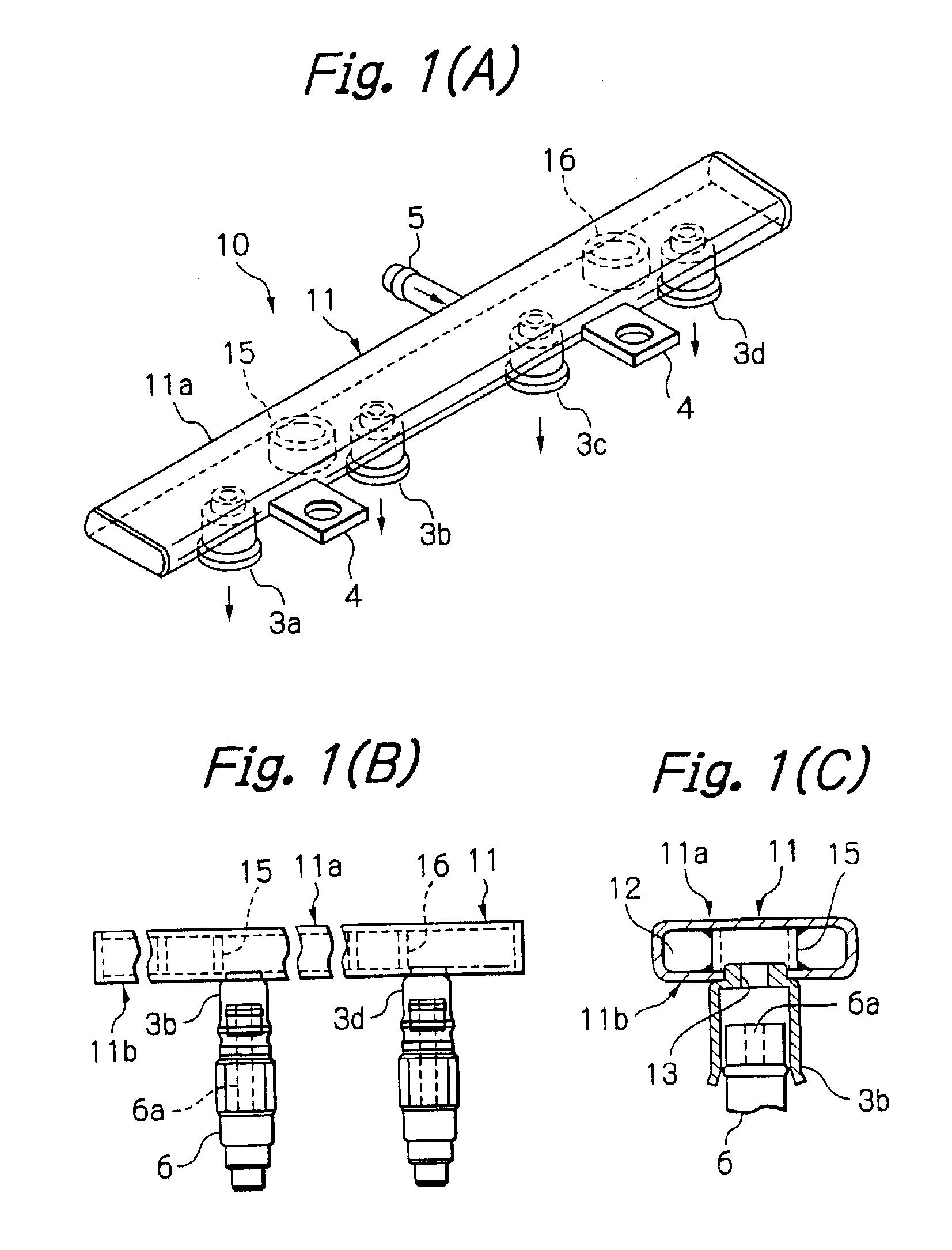
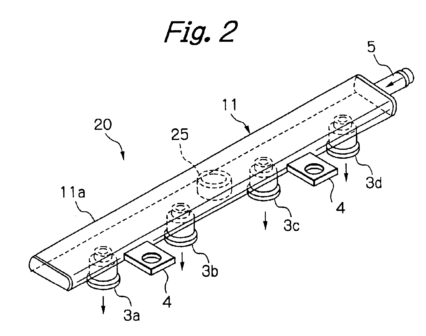
Referring to FIGS. 1A to 1C, there is shown the present invention, a fuel delivery rail assembly 10 of the so called “top feed type”, adapted to an automotive four-cylinder engine. The fuel conduit (rail) 11 comprised of flat steel pipes extends along a longitudinal direction of a crank shaft (not shown) of an engine.

At the bottom side of the conduit 11, four sockets 3a-3d for receiving tips of fuel injectors are located corresponding to the number of cylinders at predetermined angles and distances from each other. To the conduit 11, two thick and rigid brackets 4 are fixed transversely so as to mount the assembly 10 onto the engine body. Fuel flows along the arrows thereby being discharged from the sockets 3a-3d and fuel injectors (not shown) into an air intake passage or cylinders of the engine.

At the side of the conduit 11, a fuel inlet pipe 5 is fixed by brazing or welding. Although at an end of the conduit 11 it is possible to provide a fuel return pipe for transferring residua...

second embodiment

Referring to FIG. 4, there is shown the present invention. The absorbing surface 11a can absorb shock and vibration during fuel injection timing. The binding member is comprised of a solid bar 35 having a circular or a square section. The solid bar 35 also works to minimize a high-frequency sound component from the vibration noise.

third embodiment

Referring to FIGS. 5A and 5B, there is shown the present invention. The absorbing surface 11a can absorb shock and vibration during fuel injection timing. The binding member is comprised of a channel-like curved plate 45 having flange-like curved ends which are prepared for easy welding or brazing. The plate 45 also works to minimize a high-frequency sound component from the vibration noise.


PUM


Abstract

A fuel delivery rail assembly for supplying fuel to a plurality of fuel injectors in an engine is provided. The assembly includes an elongate conduit having a longitudinal fuel passage therein, a fuel inlet pipe, and a plurality of sockets. One wall of the conduit opposite to the socket mounting wall includes a flat or arcuate flexible absorbing surface. A high-frequency noise suppressing device such as a binding member is fixed within the conduit for connecting the one wall and the socket mounting wall. The binding member includes is comprised of a pipe, a bar or a rigid block. The binding member may be a body portion of an extending socket terminating with the one wall. Thus, fuel pressure pulsations and shock waves are reduced by bending of the absorbing surface, and emission of high-frequency noise is eliminated.

Description

BACKGROUND OF THE INVENTIONThis invention relates to a fuel delivery rail assembly for an internal combustion engine, especially for an automotive engine, equipped with an electronic fuel injection system. The fuel delivery rail assembly delivers pressurized fuel supplied from a fuel pump toward intake passages or chambers via associated fuel injectors. The assembly is used to simplify installation of the fuel injectors and the fuel supply passages on the engine. In particular, this invention relates to sectional constructions of a fuel conduit (fuel rail) having a fuel passage therein and connecting constructions between the conduit and sockets for receiving fuel injectors.Fuel delivery rails are popularly used for electronic fuel injection systems of gasoline engines. There are two types of fuel delivery rails; one is a return type having a return pipe and another is a non-return (returnless) type. In the return type, fuel is delivered from a conduit having a fuel passage therein ...

Claims


Application Information

Patent Timeline
IPC IPC(8): F02M55/02F02M55/04F02M55/00F02M69/46
CPCF02M55/025F02M55/04F02M2200/8084F02M2200/315F02M69/465
Inventor TSUCHIYA, HIKARISERIZAWA, YOSHIYUKIOGATA, TETSUOMIZUNO, KAZUTERUTAKIKAWA, KAZUNORI
Owner USUI KOKUSAI SANGYO KAISHA LTD
Learn More