Metal bellows accumulator

a technology of accumulators and bellows, which is applied in the direction of brake cylinders, braking systems, braking components, etc., to achieve the effect of compact manufacturing

Inactive Publication Date: 2005-03-29
ADVICS CO LTD
View PDF12 Cites 17 Cited by
  • Summary
  • Abstract
  • Description
  • Claims
  • Application Information

AI Technical Summary

Benefits of technology

In this case, when the hydraulic accumulator is applied to a brake system of an automobile, it is possible to secure not only an initial braking force (because the gas pressure is set to a value equal to or greater than 2 MPa) but also a required life of the metallic bellows unit (because the gas pressure is set to a value equal to or smaller than 9 MPa).
Preferably, the bellows portion of the metallic bellows unit includes a plurality of pleats each having a S-shaped cross section. In this case, as compared with the case where the bellows portion of the metallic bellows unit includes a plurality of pleats each having a U-shaped cross section, a minimum pitch (i.e., a pitch when the bellows portion is collapsed) of the pleats can be reduced and, therefore, the hydraulic accumulator can be manufactured compactly.

Problems solved by technology

Further, because the liquid port always communicates with a liquid chamber to which an inner circumferential surface of a bellows portion of the metallic bellows unit is exposed via a communication passage, it is unnecessary to employ a sealing structure for preventing the atmospheric pressure from acting on the inner side of the bellows portion of the metallic bellows unit.

Method used


Image

  • Metal bellows accumulator
  • Metal bellows accumulator
  • Metal bellows accumulator

Examples


Embodiment Construction

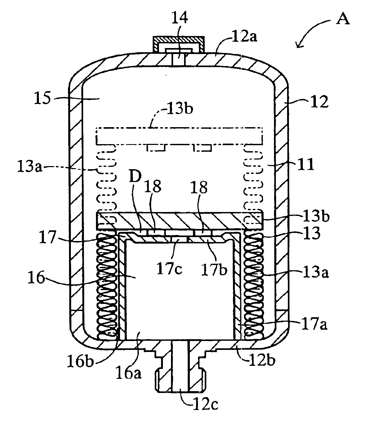
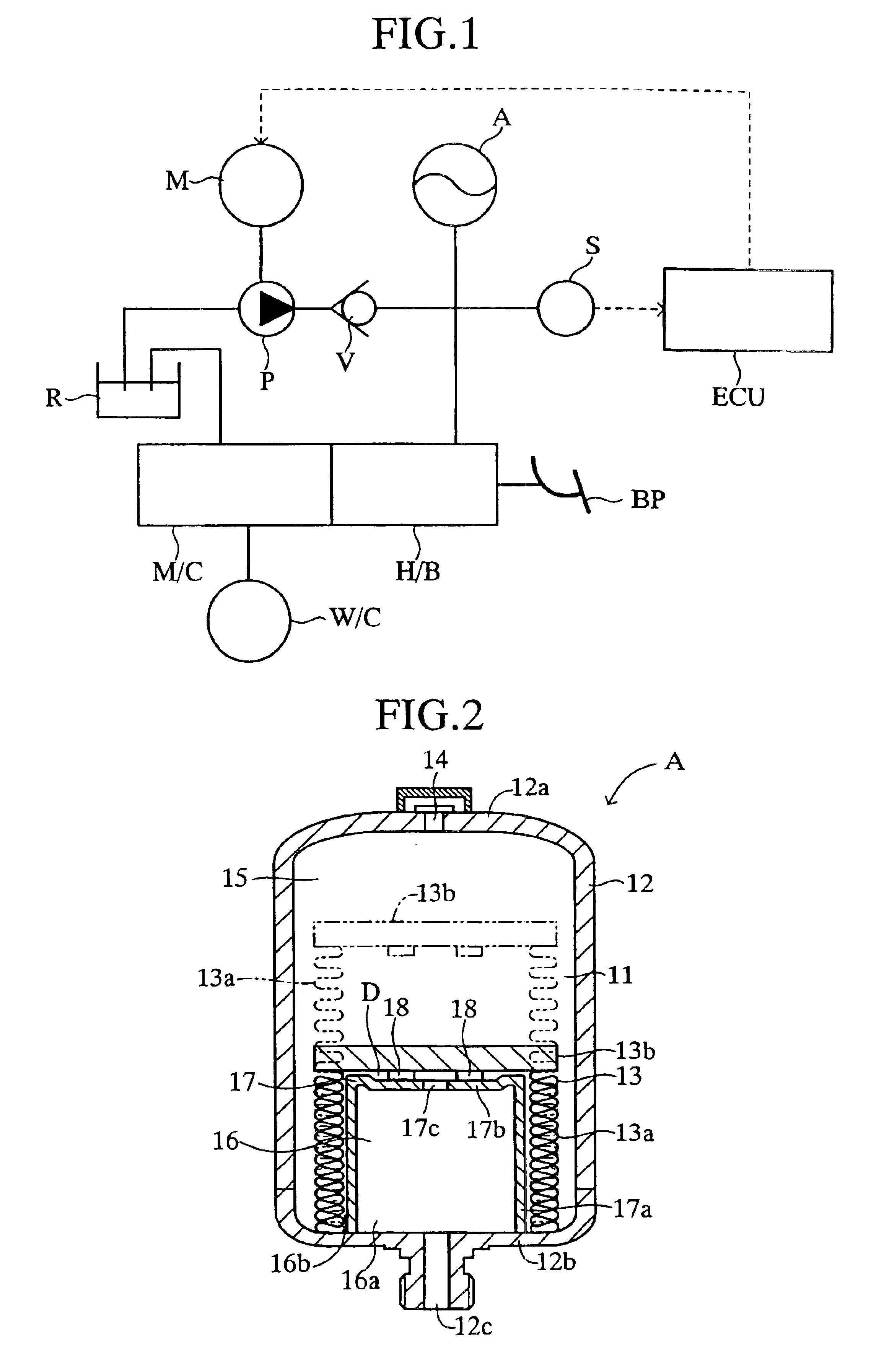
A preferred embodiment of the present invention will now be described with reference to the drawings. FIG. 1 schematically shows a brake system of an automobile to which a metal bellows accumulator A according to the present invention is applied. In the present embodiment, a pressurized liquid from a hydraulic pump P driven by an electric motor M is accumulated in the hydraulic accumulator A via a check valve V, and is then supplied to a hydraulic booster H / B, which is operable in response to depression of a brake pedal BP, and is used to produce assist pressure for a master cylinder M / C.

Further, in the present embodiment, the hydraulic pump P is connected to a reservoir R; and the master cylinder M / C is connected to both the reservoir R and a wheel cylinder W / C. The driving of the electric motor M is controlled by an electric control unit ECU in accordance with a signal from a pressure sensor S, which detects the pressure of the pressurized liquid accumulated in the hydraulic accum...


PUM


Abstract

In a metal bellows accumulator, a metallic bellows unit is disposed within a pressure space defined in a main shell, and one end of the metallic bellows unit is fixedly secured to one end wall of the main shell. The metallic bellows unit sections the pressure space into an outer chamber serving as a gas chamber in which a pressurized gas is enclosed, and an inner chamber serving as a liquid chamber communicating with a liquid port formed in the end wall of the main shell. A stopper (auxiliary shell) for limiting collapsing movement of the metallic bellows unit is disposed within the liquid chamber and has a communication passage hole. The liquid port always communicates with a liquid chamber to which an inner circumferential surface of a bellows portion of the metallic bellows unit is exposed via the communication passage hole.

Description

TECHNICAL FIELDThe present invention relates to a hydraulic accumulator for accumulating a pressurized liquid, and more particularly to a metal bellows accumulator whose interior is sectioned by means of a metallic bellows unit into a gas chamber, in which a pressurized gas is enclosed, and a liquid chamber communicating with the exterior.BACKGROUND ARTA certain conventional hydraulic accumulator of the described type includes a shell defining a pressure space, and a metallic bellows unit which is disposed within the pressure space and whose one end is fixedly secured to an end wall of the shell. The metallic bellows unit sections the pressure space into an outer chamber serving as a gas chamber, in which a pressurized gas is enclosed, and an inner chamber serving as a liquid chamber communicating with a liquid port formed in the end wall of the shell. This conventional hydraulic accumulator is disclosed in, for example, Japanese Patent Application Laid-Open (kokai) No. 2001-116003....

Claims


Application Information

Patent Timeline
Patent Type & Authority Patents(United States)
IPC IPC(8): F15B1/00F15B1/22F15B1/10F15B1/08
CPCB60T13/14B60T17/06F15B1/027F15B1/103F15B1/22F15B2201/415F15B2201/205F15B2201/3153F15B2201/3157F15B2201/411
Inventor SUZUKI, KENICHITAKAHARA, YASUOKONDO, HIROSHIKAWAMURA, TOSHIHIKO
Owner ADVICS CO LTD
Why Eureka
Try Eureka