Electrical hand tool device

a hand tool and electric technology, applied in the direction of electrical equipment, transmission systems, transmission, etc., can solve the problems of inability to transmit information to the external telecommunication transmitter, difficulty and substantial expense of the telecommunication receiver of the electrical hand tool device, and the need for continuous communication operation

Inactive Publication Date: 2005-03-29
METABOWERKE
View PDF12 Cites 120 Cited by
  • Summary
  • Abstract
  • Description
  • Claims
  • Application Information

AI Technical Summary

Benefits of technology

In an advantageous further development of the invention writing into the storage means of the electrical hand tool device is possible and the authorization code stored therein can be changed through transmission of a required control command to the transmitting / receiving means of the electrical hand tool device thereby switching the control electronics and the storage means into a programming mode. The newly stored authorization code is then transmitted to the internal transmitting / receiving means of the device, preferably via digitised code signals.

Problems solved by technology

I.e. a permanent, however, discontinuous communication operation is required to maintain the operativeness of the device.
The telecommunication receiver of the electrical hand tool device causes difficulties and substantial expense.
In addition, transmission of information to the external telecommunication transmitter is not possible.
Permanent locking or release of the device is not possible.

Method used


Image

  • Electrical hand tool device
  • Electrical hand tool device
  • Electrical hand tool device

Examples


Embodiment Construction

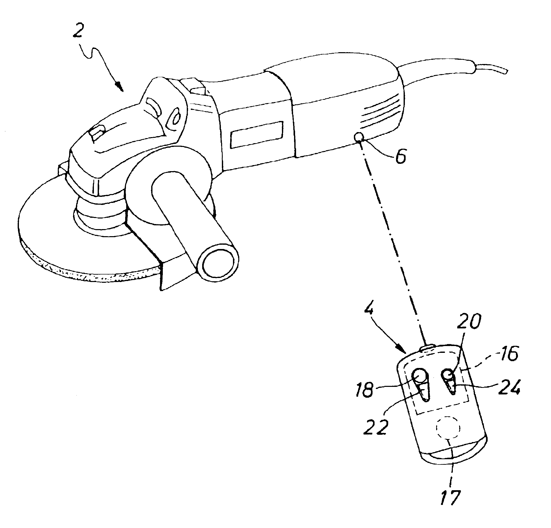
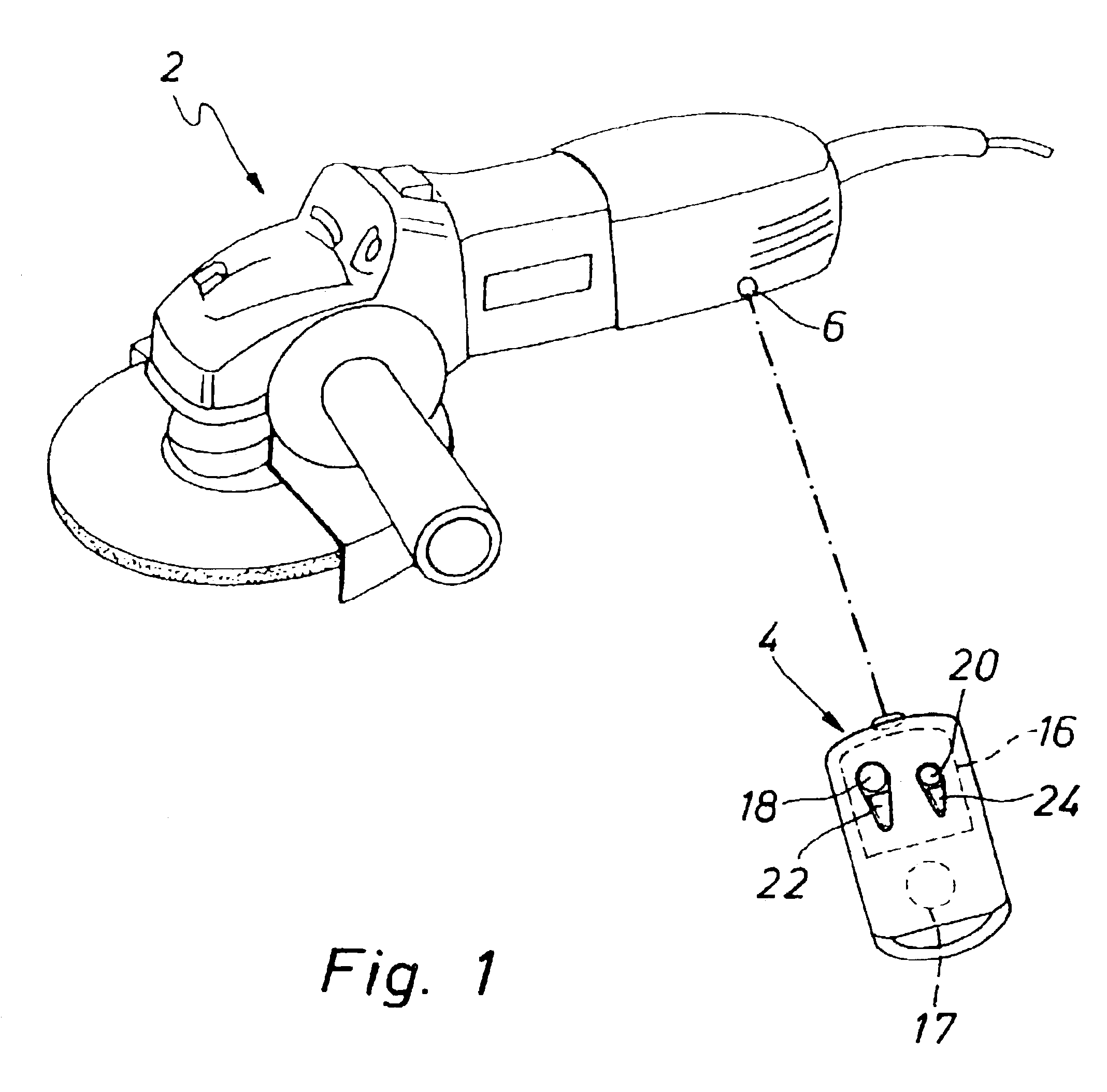
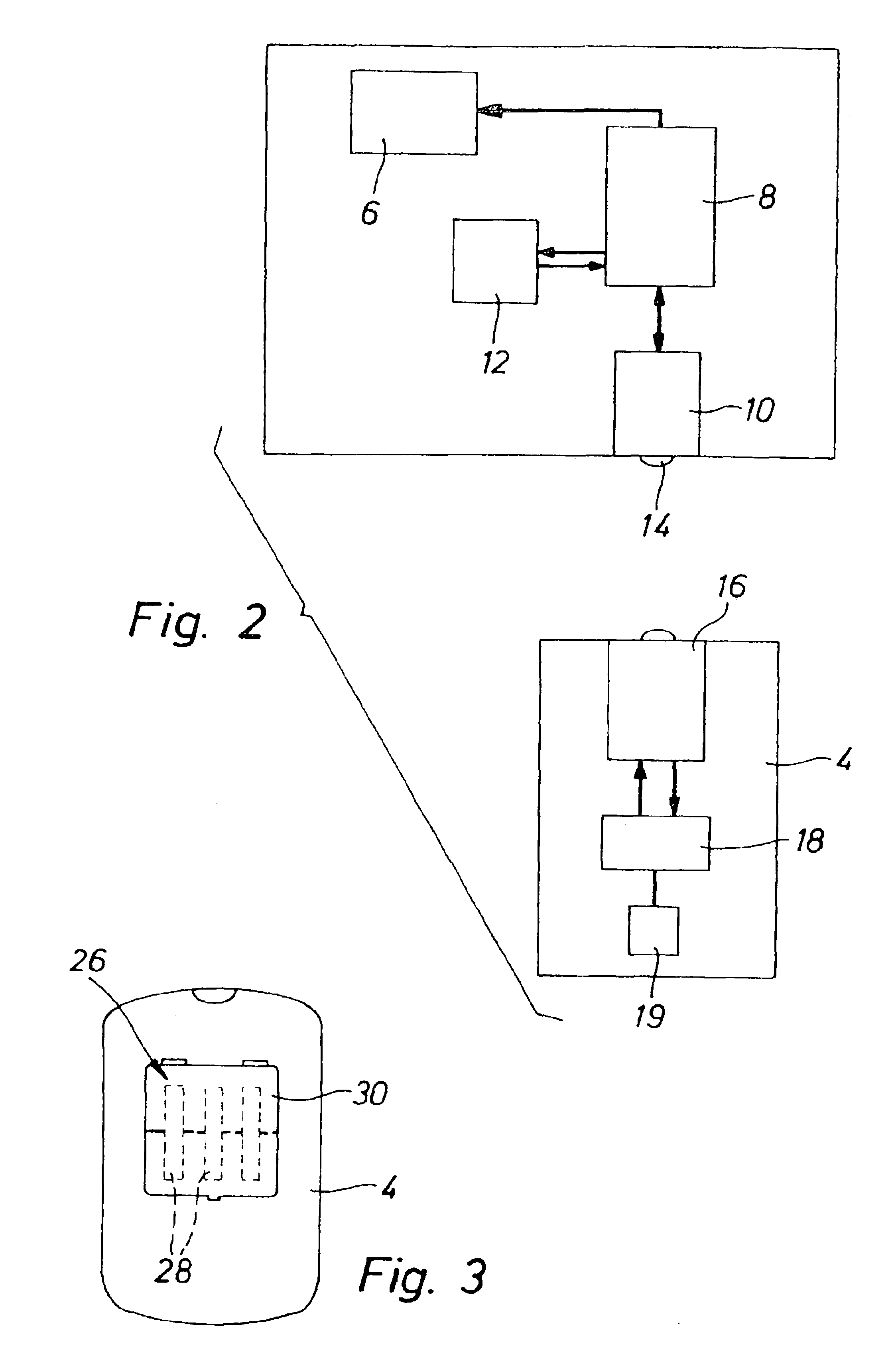
FIG. 1 shows an electrical hand tool device 2 and an external auxiliary or control device 4 for changing the operation state of the electrical hand tool device 2 between an operation locking state and an operation release state. Towards this end, the electrical hand tool device 2 has a processor-controlled control electronics 8 acting on the motor control 6, a transmitting / receiving means 10, and a storage means 12 in which an authorization code is stored. The internal transmitting / receiving means 10 of the device communicates in a wireless and contact-free fashion, preferably via an infrared interface 14. The control electronics 8 is designed to place the electrical hand tool device 2 into a permanent operation locking state or an operation release state depending on the signal received from the transmitting / receiving means 8.

The external device 4 comprises a transmitting / receiving means 16 which is supplied with electric voltage from a round battery cell 17, and a control switch 1...


PUM

PropertyMeasurementUnit
mechanicalaaaaaaaaaa
transmissionaaaaaaaaaa
electrical poweraaaaaaaaaa

Abstract

An electrical hand tool device (2) comprises a control electronics (8) and a transmitter and receiver (10) which is responsive in a wireless and contact-free fashion, and with a storage medium (12) in which an authorization code is stored, wherein an operation locking state and an operation release state can be differentiated, and with an external transmitter and receiver means (16) which is accommodated in a separate portable device (4), wherein communication with the transmitter and receiver means (10) of the electrical hand tool device can be produced in a defined fashion through actuation of the external transmitter and receiver means (16) to change the operation state, and communication is provided only to change the operation state and optionally to change the authorization code.

Description

This application claims Paris Convention priority of DE 102 38 710.9 filed Aug. 23, 2002 the complete disclosure of which is hereby incorporated by reference.BACKGROUND OF THE INVENTIONThe invention concerns an electrical hand tool device comprising a control electronics and a transmitting / receiving means which is responsive in a wireless and contact-free fashion, and a storage means in which an authorization code is stored, wherein an operation locking state and an operation release state can be differentiated, and with an external transmitting / receiving means which is disposed in a separate portable device. The above-mentioned differentiation between an operation locking state and an operation release state prevents unauthorized use by putting the device into a locking state in which the electrical hand tool device can no longer be operated. The electrical hand tool device is thereby protected against theft, since there is little to be gained thereby.DE 100 29 138 A1 discloses an ...

Claims


Application Information

Patent Timeline
Patent Type & Authority Patents(United States)
IPC IPC(8): B25F5/00
CPCB25F5/00
Inventor WIESNER, BERNDSCHWARZ, STEFANPLIETSCH, REINHARDGAERTNER, MARCONEIKA, PATRICK
Owner METABOWERKE
Why Eureka
Try Eureka