Water electrolysis cell
- Summary
- Abstract
- Description
- Claims
- Application Information
AI Technical Summary
Benefits of technology
Problems solved by technology
Method used
Image
Examples
##ventive example 1
INVENTIVE EXAMPLE 1
In Inventive Example 1, a water electrolysis cell 21 as a single cell shown in FIG. 4 was produced.
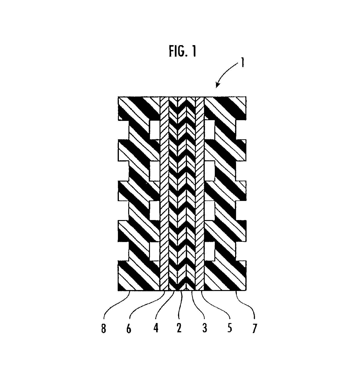
The water electrolysis cell 21 has a solid polymer electrolyte membrane (cation ion exchange membrane) 2, a pair of catalytic layers 3, 4, and a pair of porous current distributors 5, 6, which are identical to the solid polymer electrolyte membrane 2 of the water electrolysis cell 1 shown in FIG. 1, all sandwiched between a pair of electrode plates 22, 23 having respective gas / liquid passages. The electrode plates 22, 23 are supported by respective nonconductive supports 24, 25 held against respective outer surfaces thereof, and are fastened together by bolts 26 and nuts 27.
The water electrolysis cell 21 has an upper gas / liquid transport manifold 28 extending transversely through upper portions of the electrode plates 22, 23 and the supports 24, 25 and a lower gas / liquid transport manifold 29 extending transversely through lower portions of the electrode plates 22, 2...
##ventive example 2
INVENTIVE EXAMPLE 2
The same water electrolysis cell 21 as the water electrolysis cell 21 according to Inventive Example 1 except that a cation ion exchange membrane having a thickness of 100 μm was used as the solid polymer electrolyte membrane 2 was prepared. Water is electrolyzed by the water electrolysis cell 21 at a current density of 1.4 A / cm2 at a water temperature of 80° C., and changes with time of the current efficiency and the voltage efficiency with respect to the initial current and voltage were measured. The results are shown in FIG. 5.
##ventive example 3
INVENTIVE EXAMPLE 3
The same water electrolysis cell 21 as the water electrolysis cell 21 according to Inventive Example 1 except that a cation ion exchange membrane having a thickness of 100 μm was used as the solid polymer electrolyte membrane 2 and the anode catalyst was made of an oxide of an Ru—Ir—Fe alloy having a molar ratio Ru:Ir:Fe=1:1:0.1 was prepared. Water is electrolyzed by the water electrolysis cell 21 under the same conditions as with Inventive Example 2, and changes with time of the voltage efficiency with respect to the initial voltage were measured. The results are shown in FIG. 5.
PUM
| Property | Measurement | Unit |
|---|---|---|
| Substance count | aaaaa | aaaaa |
| Substance count | aaaaa | aaaaa |
| Substance count | aaaaa | aaaaa |
Abstract
Description
Claims
Application Information
 - R&D
- Intellectual Property
- Life Sciences
- Materials
- Tech Scout
- Unparalleled Data Quality
- Higher Quality Content
- 60% Fewer Hallucinations
Browse by: Latest US Patents, China's latest patents, Technical Efficacy Thesaurus, Application Domain, Technology Topic, Popular Technical Reports.
© 2025 PatSnap. All rights reserved.Legal|Privacy policy|Modern Slavery Act Transparency Statement|Sitemap|About US| Contact US: help@patsnap.com


