Method and apparatus for manufacturing filters

a filter and filter material technology, applied in the field of devices and methods making filters, can solve the problems of difficult control, potting material, and fiber material burning, and achieve the effect of shortening the amount of time that fibers need to be exposed to the heater

Inactive Publication Date: 2005-03-29
NXSTAGE MEDICAL
View PDF19 Cites 77 Cited by
  • Summary
  • Abstract
  • Description
  • Claims
  • Application Information

AI Technical Summary

Benefits of technology

One of the benefits of the inventive method is that it speeds production. The amount of time that the fibers need to be exposed to the heater is very short. It follows that the heater needs to be one that can be heated up and cooled quickly or moved toward and away from the fibers before and after they have been melted satisfactorily. In an embodiment of a produc

Problems solved by technology

While still liquid, the potting material, however, has a tendency to flow into the centers of the filter fibers like water running up a straw in a glass of soda.
The problem with the two-phase approach is that it requires multiple curing steps, which is undesirable from a production

Method used


Image

  • Method and apparatus for manufacturing filters
  • Method and apparatus for manufacturing filters
  • Method and apparatus for manufacturing filters

Examples


Embodiment Construction

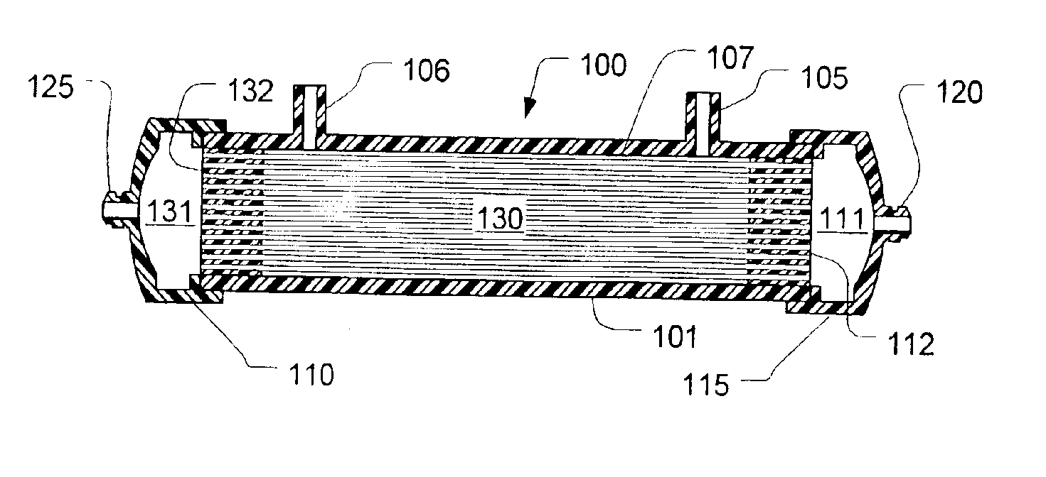
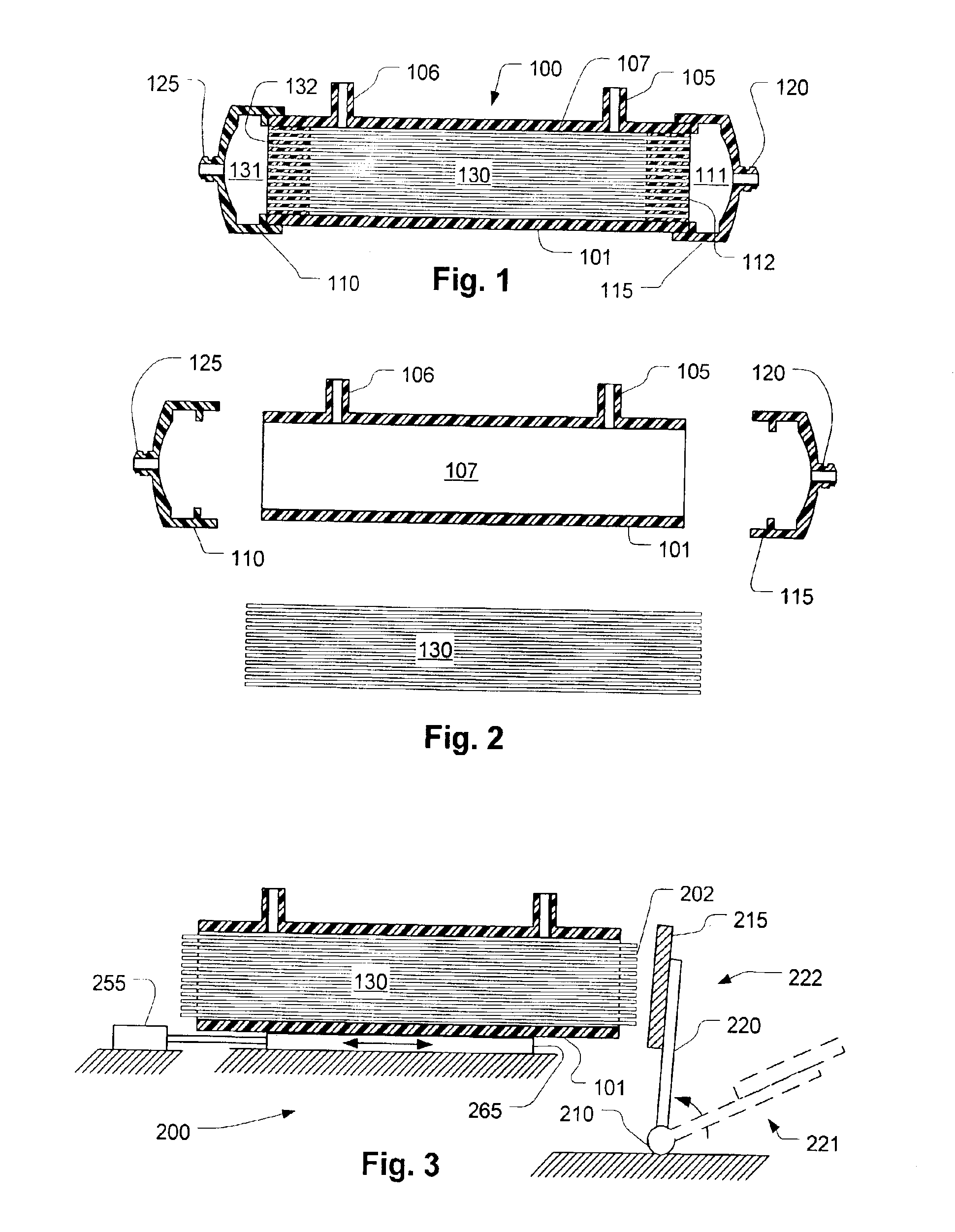
Referring now to FIG. 1, a filter 100 has a housing 101 that is generally cylindrical in shape with one or more filtrate ports 105 and 106. In a dialysis application, these filtrate ports 105 and 106 would be connected respectively to a source and drain for dialysate. A bundle of fibers 130 rests within the housing. Each fiber is cylindrical in shape with its interior in communication with header spaces 131 and 111 at respective ends thereof. Respective plugs of potting material 132 and 112 form headers that prevent fluid in the header spaces 131 and 111 from flowing into the internal volume 107 between the fibers which communicates with the filtrate ports 105 and 106. Blood ports 120 and 125 provide access to the header spaces 131 and 111.

FIG. 2 shows an exploded diagram of the components used for making the filter. The filter tube bundle 130 is inserted loosely into the filter housing 101. Later, end caps 110 and 115 are attached, usually by well-known bonding techniques. The filt...


PUM

PropertyMeasurementUnit
Temperatureaaaaaaaaaa
Timeaaaaaaaaaa
Poweraaaaaaaaaa

Abstract

A problem in the manufacture of filters using tubular membrane bundles is keeping potting material from flowing into the openings at the ends of the tubes. A preferred embodiment of a method for manufacturing a tubular membrane filter employs a non-contact heat source such as radiant heating to melt the tips of the tubular membranes. This prevents the migration of potting material into the tubes when the potting material is flowed into the ends of tube bundles during the manufacturing process for a filter.

Description

FIELD OF THE INVENTIONThe present invention relates generally to devices and methods making filters, particularly for the stage of making tubular fiber filters in which the ends of filter fibers are potted in liquid which is later hardened and cut to form a headers at each end of a fiber bundle.BACKGROUND OF THE INVENTIONDialysis, hemofiltration, and other blood treatments that make use of microtubular filters have prolonged the lives of patients with acute or chronic renal insufficiency. In hemodialysis, for example, a semi-permeable membrane or filter is used to remove unwanted substances from the blood while adding desirable components by the process of diffusion across the filter. In Hemofiltration, electrolyte is drawn through a microporous membrane filter and replaced with properly balanced fluid. The principal dialyzer used in the United States is the hollow fiber or capillary dialyzer. In the hollow fiber or capillary dialyzer, membrane material is spun into fine capillaries...

Claims


Application Information

Patent Timeline
IPC IPC(8): B29C45/14B01D63/02B01D63/06B01D65/00
CPCB01D63/021B01D63/022B01D65/003B29C45/14385B01D63/061B29L2031/14B01D63/0224B01D63/0222
Inventor STILLIG, MARTIN
Owner NXSTAGE MEDICAL
Why Eureka
Try Eureka