
Magnetic component

a technology of magnetic components and components, applied in the field of magnetic components, can solve the problems of high q-factors, high cost of equipment manufacturers, and high cost, and achieve the effect of increasing inductan

Inactive Publication Date: 2005-03-29
INFINEON TECH AG
View PDF11 Cites 8 Cited by
  • Summary
  • Abstract
  • Description
  • Claims
  • Application Information

AI Technical Summary

Benefits of technology

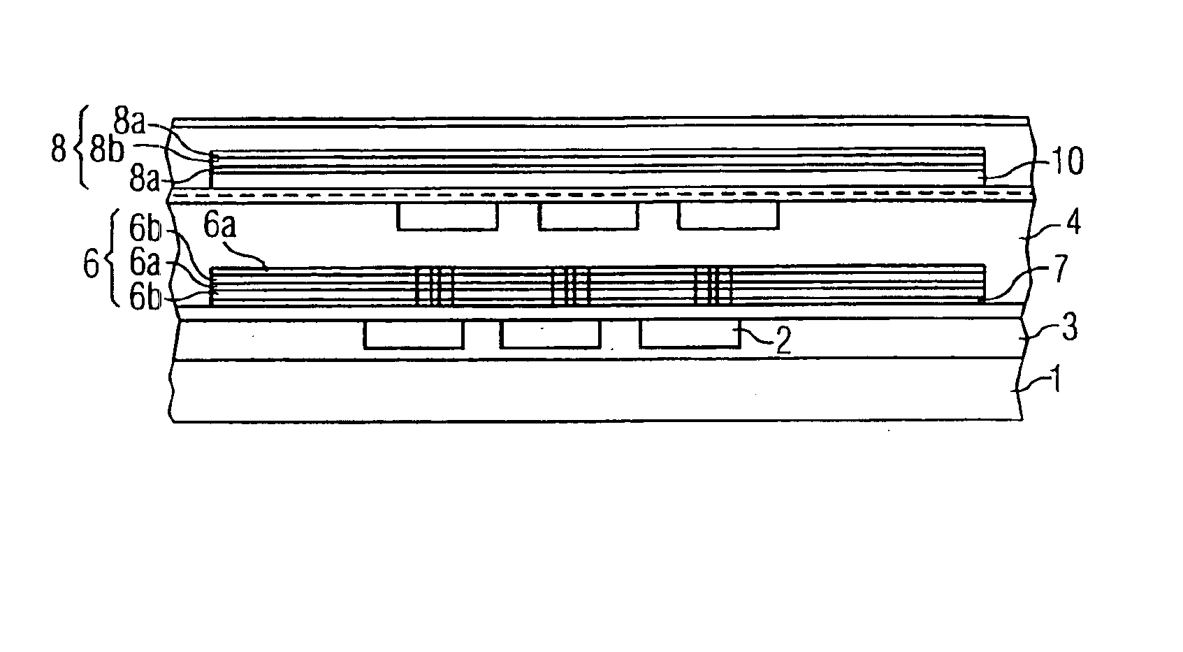
[0020]The magnetic component according to the invention uses at least two different layers or layer sequences composed of magnetic material for carrying and amplifying the magnetic flux, that is to say the first and the second layer are produced using different layer production processes or process steps. The use of two different layers which may, however, have the same material composition allows a magnetic circuit with a locally matched domain alignment to be formed by the magnetic conductors. The magnetic component according to the invention accordingly makes it possible to achieve considerable improvements in the component parameters, in particular a considerable increase in the Q-factor. In this case, the magnetic circuit formed by the magnetic conductors does not necessarily need to be closed. Furthermore, the first direction, in which the domains in the first layer are aligned, and the second direction, in which the domains in the second layer are aligned, do not necessarily need to be different.
[0024]The previously proposed integrated coils, which were based essentially on only a single magnetic layer, resulted in the repeated occurrence of sections of the magnetic circuits in which the magnetic field was oriented parallel to the domains. These sections of the magnetic circuit thus contributed nothing to amplification of the magnetic field at high frequencies, even though these sections were composed of magnetic material. The magnetic component according to the present invention avoids such sections by using at least two magnetic conductors composed of two different layers. The alignment of the domains in the layers and / or the three-dimensional arrangement of the layers with respect to one another can accordingly be chosen such that sections in which the magnetic field is oriented parallel to the domains can largely be avoided. This leads to considerably more effective utilization of the magnetic material, which in turn results in the magnetic component having considerably better parameters.
[0025]Furthermore, the magnetic flux is kept away from the substrate and away from the winding, so that the eddy current losses at these points are minimized. The magnetic component according to the invention can accordingly also be formed on conductive substrates. Since the inductance, for example, of a coil is essentially directly proportional to the permeability μr of the core material, the Q-factor of the coil also depends directly on the permeability μr of the core material. A high permeability μr allows considerably smaller coils to be produced. The reduction in the size of the electrical conductor length that results from this leads to an improvement in the Q-factor, due to the reduced resistive losses.
[0026]According to one preferred embodiment of the magnetic component according to the invention, at least one of the magnetic conductors is slotted. Furthermore, it is preferable for at least one of the magnetic conductors to be a laminate composed of magnetic layers and electrically insulating layers. Slotting and / or lamination of the magnetic material makes it possible to largely avoid eddy current losses in the magnetic material.
[0029]According to a further preferred embodiment of the magnetic component according to the invention, the electrical conductor is formed from copper. It is furthermore preferable for the electrical conductor to be in the form of two metalization planes, which are connected by means of vias. In this case, it is particularly preferable for contact holes, through which the vias are passed, to be provided in the first layer of magnetic material. Appropriately large edge areas of the magnetic conductor make it possible to prevent edge domains from penetrating into the magnetically active areas of the magnetic conductor.
[0030]According to a further preferred embodiment of the magnetic component according to the invention, a second electrical conductor having at least one turn is provided, with the second magnetic conductor being arranged within the turn of the second electrical conductor. Appropriate interconnection of the first and of the second electrical conductors thus makes it possible to produce either a transformer or a coil with increased inductance. If a magnetic component such as this is used as a coil, then it is preferable for the first electrical conductor and the first magnetic conductor together to form a first helical coil, and for the second electrical conductor and the second magnetic conductor together to form a second helical coil, with the two helical coils being connected in series and having opposite polarity.

Problems solved by technology

The mounting, the soldering and the testing of the individual components, which are becoming ever smaller, in this case are the cause of a major proportion of the costs for the equipment manufacturers.
Although these coils have high Q-factors, they are relatively expensive.
Unfortunately, spiral coils such as these also have a large number of disadvantages which have until now prevented higher Q-factors from being achieved.
Furthermore, the magnetic flux element which flows through the electrical conductors causes eddy currents in the conductor material, which in turn results in additional losses.
However, the main problem of planar spiral coils is in the direction of the magnetic flux since, due to the alignment of the spiral coils, the majority of this magnetic flux is necessarily carried through the substrate.
Despite major efforts by the component manufacturers, it has until now not been possible to develop integrated spiral coils with a Q-factor of more than 15 for large-scale production.
Since the magnetic field H is at right angles to the magnetic layer in all these coil concepts, the way in which the magnetic flux is carried is, however, highly ineffective.
Furthermore, a closed magnetic flux can be achieved, by virtue of the technology, only with great difficulty, and air gaps between the layers decrease the effective permeability of the flux circuit.
In this case, unfortunately, it has been found that although the proposed helical coils with ferromagnetic cores make it possible to increase the Q-factors of the coils, the increase in the Q-factor is, however, generally not sufficient to justify the likewise increased production cost for manufacturing the ferromagnetic cores.

Method used


Image

  • Magnetic component
  • Magnetic component
  • Magnetic component

Examples


Embodiment Construction

orm a first helical coil, and for the second electrical conductor and the second magnetic conductor together to form a second helical coil, with the two helical coils being connected in series and having opposite polarity.

BRIEF DESCRIPTION OF THE DRAWING

[0031]The invention will be described in more detail in the following text with reference to the figures in the drawing, in which:

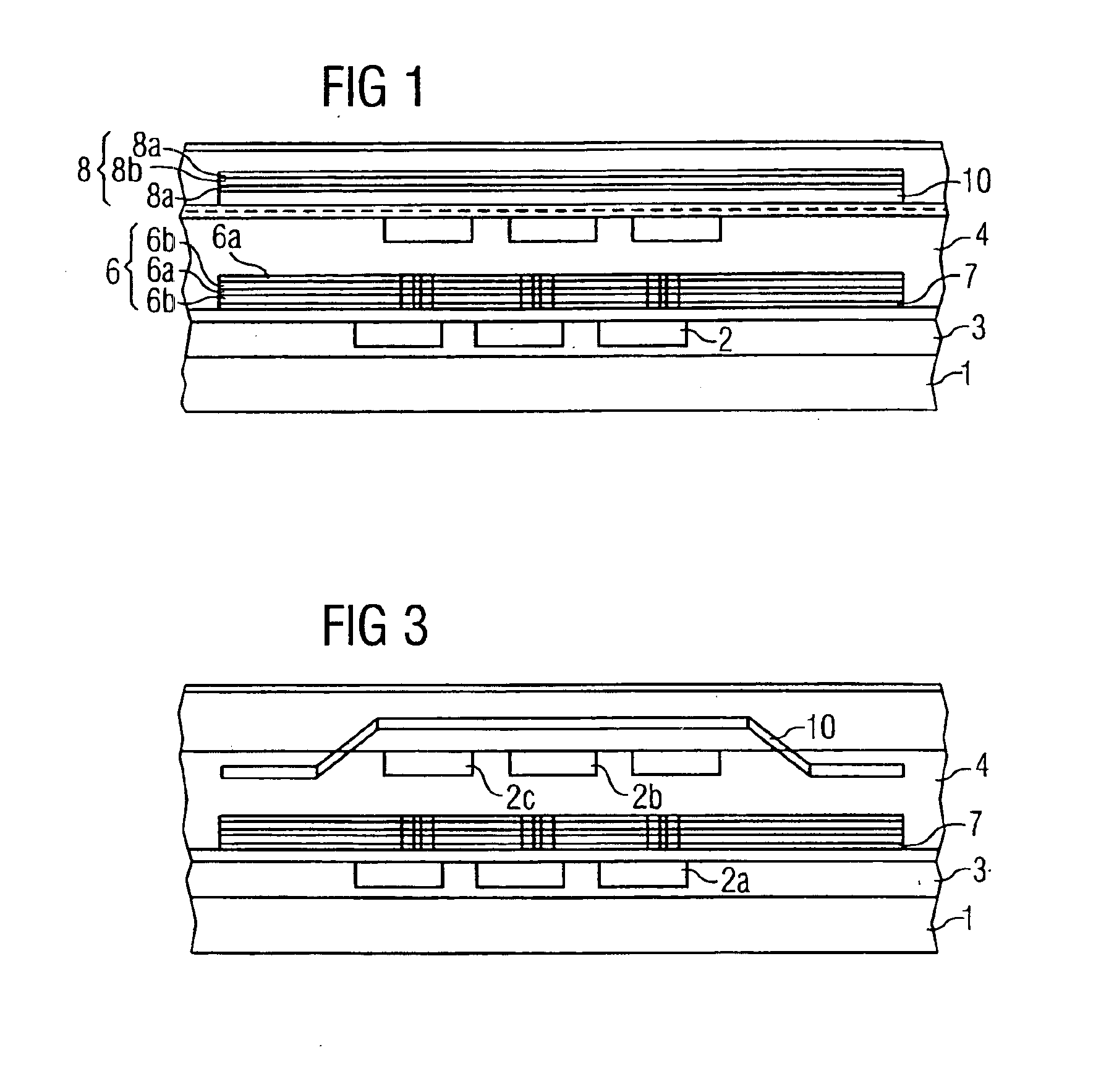
[0032]FIG. 1 shows a first embodiment of the magnetic component according to the invention,

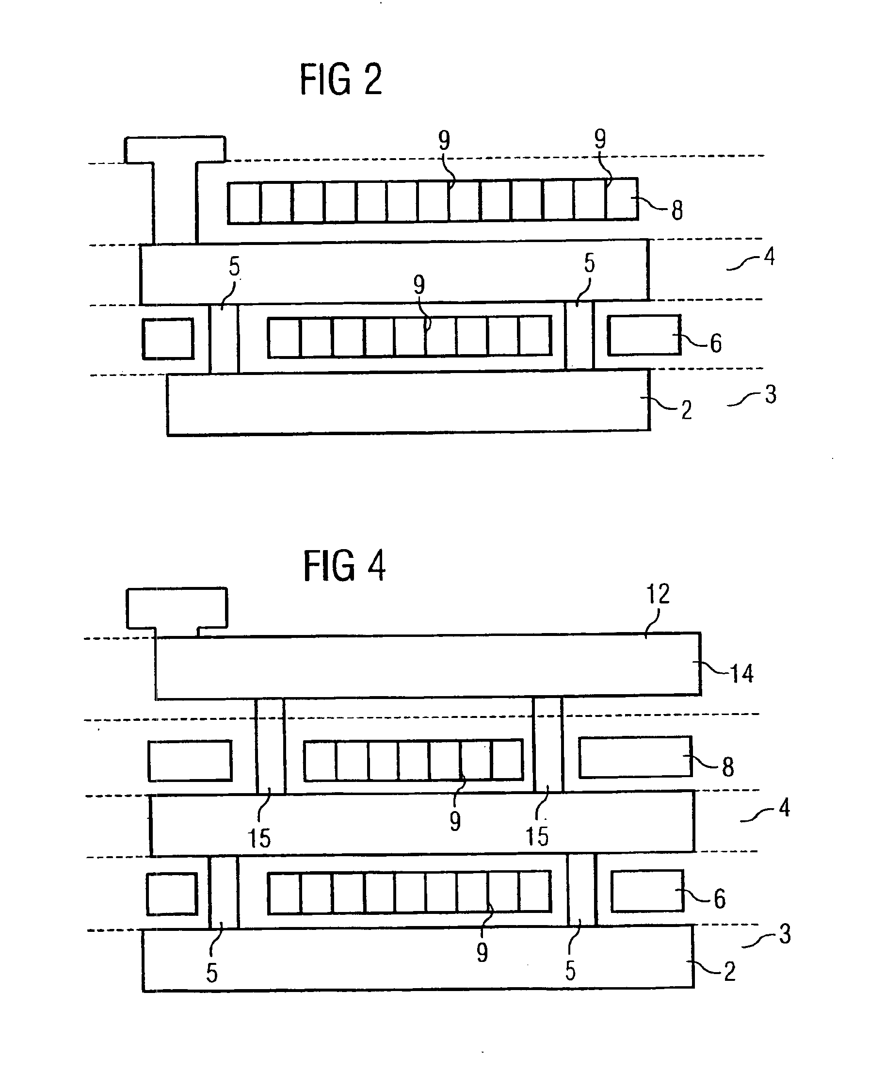
[0033]FIG. 2 shows a further cross-sectional view of the first embodiment of the magnetic component according to the invention,

[0034]FIG. 3 shows a further embodiment of the magnetic component according to the invention,

[0035]FIG. 4 shows a further embodiment of the magnetic component according to the invention,

[0036]FIG. 5 shows a further embodiment of the magnetic component according to the invention, and

[0037]FIG. 6 shows a further embodiment of the magnetic component according to the invention.

DESCRIPTION OF THE ...


PUM

PropertyMeasurementUnit
frequencyaaaaaaaaaa
frequencyaaaaaaaaaa
frequencyaaaaaaaaaa

Abstract

The magnetic component uses at least two different layers of magnetic material for carrying and amplifying the magnetic flux. The use of two different layers which may, however, have the same material composition allows the magnetic conductors to form a magnetic circuit with a locally matched domain alignment. The magnetic component accordingly allows considerable improvements to be achieved in the component parameter, in particular a considerable increase in the Q-factor.

Description

CROSS REFERENCE TO RELATED APPLICATION[0002]This application is a continuation of copending International Application No. PCT / EP02 / 08295 filed Jul. 25, 2002 which designates the United States, and claims priority to German application no. 101 44 380.3 filed Sep. 10, 2001.TECHNICAL FIELD OF THE INVENTION[0003]The present invention relates to a magnetic component. The present invention relates in particular to a magnetic component which is integrated with other components on a substrate, for example an integrated inductance or an integrated transformer.BACKGROUND OF THE INVENTION[0004]Passive magnetic components, such as coils or transformers, are required for a large number of applications. For example, at the moment, up to 300 passive components are processed in a mobile radio telephone, with major functions being carried out by magnetic components. Every extension in function, irrespective of whether this is a dual band or dual mode extension, increases the number further. The moun...

Claims


Application Information

Patent Timeline
Patent Type & Authority Patents(United States)
IPC IPC(8): H01F17/00H01L23/52H01L23/522H01L23/64H01L23/58H01F41/04
CPCH01F17/0006H01L23/5227H01L23/645H01F17/0013H01F17/0033H01F41/042H01F41/046Y10T428/32H01L2924/3011H01L2924/0002Y10T428/12465H01L2924/00
Inventor AHRENS, CARSTENBARTL, ULFHARTUNG, WOLFGANGLOSEHAND, REINHARDWERTHMANN, HUBERT
Owner INFINEON TECH AG
Learn More