
Method and apparatus for the automatic real-time detection and correction of red-eye defects in batches of digital images or in handheld appliances

a technology of automatic real-time detection and correction, applied in the field of digital image processing, can solve the problems of disadvantages of prior art approach, almost unnoticeable to an end user, and probably the most common defect in pictures processed, and achieve the effect of accurate and automated

Inactive Publication Date: 2005-03-29
LUMERO INC +1
View PDF54 Cites 189 Cited by
  • Summary
  • Abstract
  • Description
  • Claims
  • Application Information

AI Technical Summary

Benefits of technology

An advantage of the present invention is to provide a means of correcting red-eye defects which operates uniformly on both pixels which are members of a defect and its bounding region thus avoiding the need to determine individually if pixels in the neighborhood of said defect are members of the defect and to subsequently apply correcting algorithms to such pixels on an individual basis.

Problems solved by technology

This is probably the most common defect in pictures processed from amateur and consumer photography.
Such means must be efficient in terms of computing resources and must still be fast enough on low-end embedded appliances to be practically unnoticeable to an end user.
However, disadvantages are associated with this prior art approach.
Therefore, the one disadvantage is the delay between the time when the first flashlight appears and the time when the picture is actually taken.
In addition, this technique is inefficient energy wise, with the need for multiple flashes for a single image.
Further, this prior art approach cannot solve the red-eye problem in photographs that have already been taken.
One disadvantage is that it cannot automatically detect the red eyes, but rather requires the user intervention to precisely locate the positions of the red pupils.
Another disadvantage of this prior art approach is that the red-eye region is often not a circular region.
In addition, the black circle may not be able to cover the peripheral area such as the pink ring of the red-eye region.
The disadvantage of this prior art scheme is that some kind of painting skill is needed for the user to paint over the red eyes.
Another disadvantage is that the correction of the red-eye is not done automatically, but rather manually.
Thus, the result of this type of correction is often quite noticeable and undesirable, and sometimes destroys the natural appearance of the eyes in the image.
However these techniques are dependent of the eye region being large enough to partition into a number of distinct regions and will only work in a subset of cases.
Both patents adopt quite complex, and thus resource intensive, image processing techniques to detect face and eye regions in an image and subsequently verify the presence of red-eye defects.
Further, there are some disadvantages to this approach when two, or more, facial regions overlap or are in close proximity to one another, particularly when a technique is weighted heavily to detect balanced eye-pairs.
Further, this prior art patent does not propose a means of correcting a red-eye defect after it is detected.
Typically, the implementation of a neural network on a conventional computer will require significant memory and computing power.
In addition, this patent requires multiple re-scaling and rotations of the original digital images, both tasks increasing significantly the requirements for both computing power and memory storage.
Further, Wang and Zhang do not propose a detailed technique for correcting any red-eye defects but only suggest replacing the color of an identified defect pixel with a predetermined color.

Method used


Image

  • Method and apparatus for the automatic real-time detection and correction of red-eye defects in batches of digital images or in handheld appliances
  • Method and apparatus for the automatic real-time detection and correction of red-eye defects in batches of digital images or in handheld appliances
  • Method and apparatus for the automatic real-time detection and correction of red-eye defects in batches of digital images or in handheld appliances

Examples


Embodiment Construction

Briefly, the present invention includes a method and apparatus to (i) detect red-eye defects in a digital image without requiring user intervention and (ii) correct these defects by restoring the original eye color without requiring user intervention.

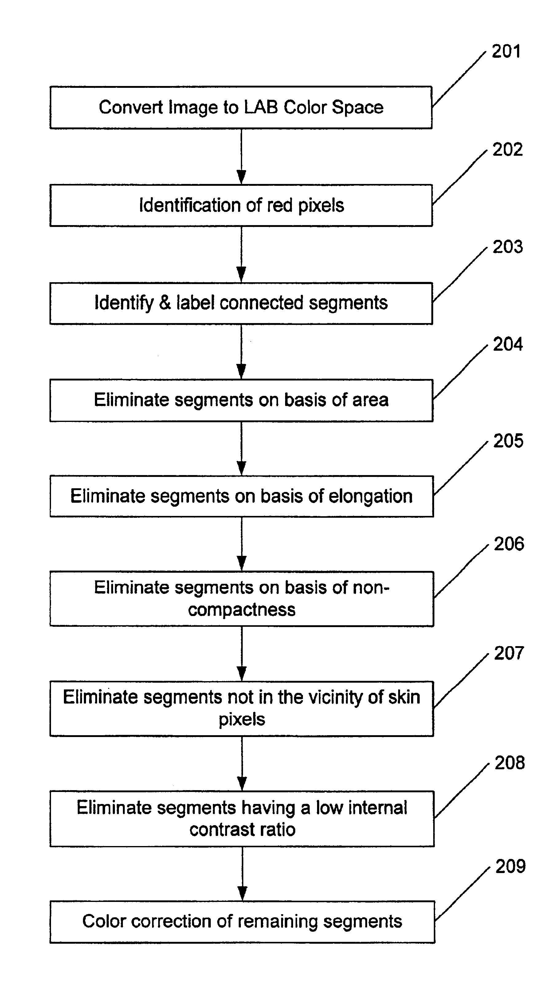
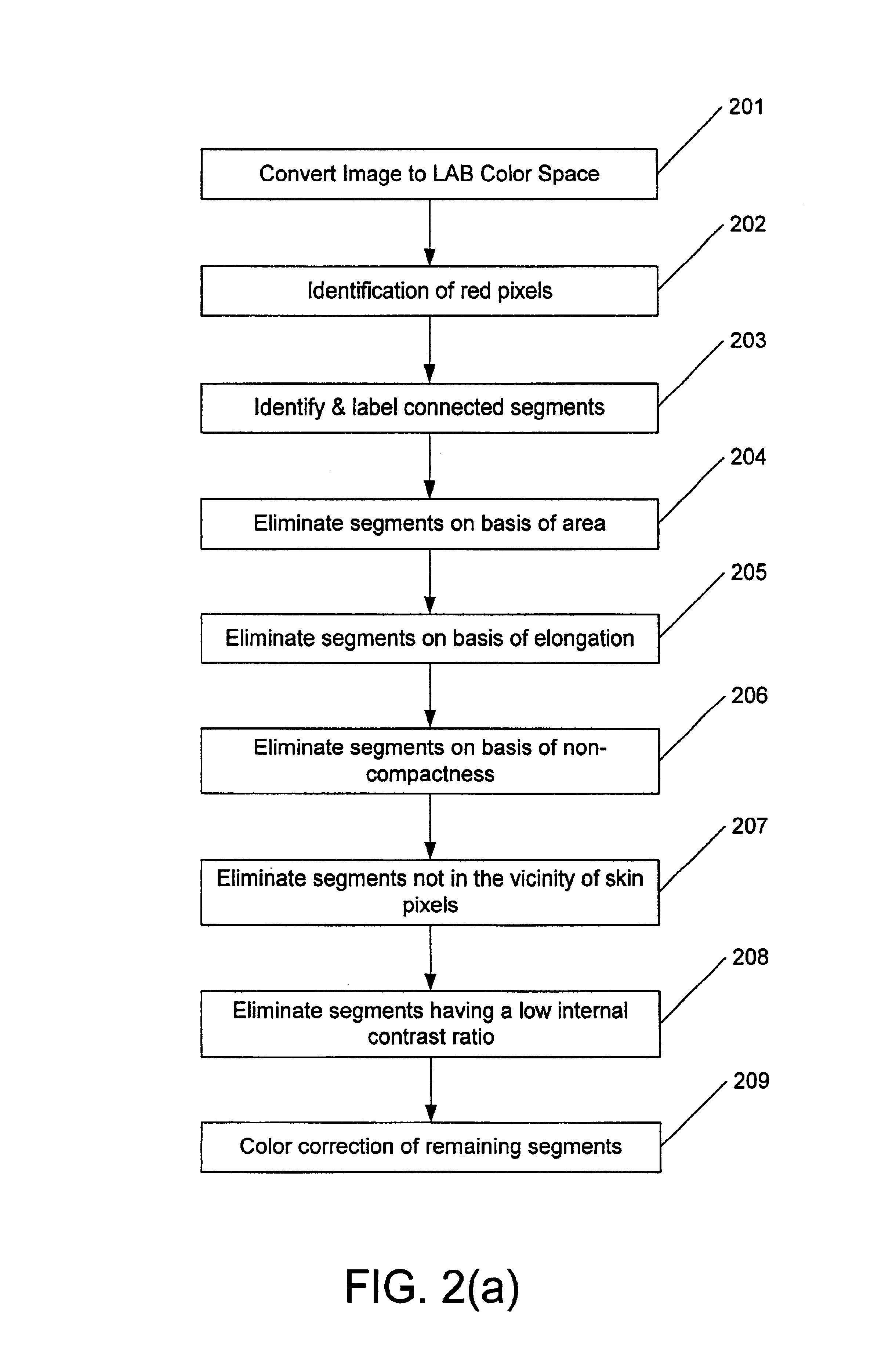
The detection step comprises the following main sub-steps: (a) the image is converted into Lab color space, whereas an Lab color space, also denoted by L*a*b* in technical publications is a well defined close to uniform Luminance chrominance color space, whereas the “L” axis denotes luminance, the “a” axis denotes red-green colors and the “b” axis denotes the blue-yellow data; (b) the image is segmented and red pixels with the correct luminosity to match red-eye defects are labeled; (c) connected segments are labeled in a single raster-scan of the image; (d) segments with inappropriate areas (too large or too small) are rejected; (e) elongated segments are rejected; (f) non-compact segments are eliminated; (g) segments which are not loc...


PUM


Abstract

An automatic, red-eye detection and correction system for digital images capable of real-time processing of images, including a red-eye detector module that determines without user intervention if a red-eye defect exists. If a defect is located in an image the portion of the image surrounding the defect is passed to a correction module that de-saturates the red components of the defect while preserving the other color characteristics of the defect region. The invention is designed to minimize the computational resources required to detect and correct red-eye defects and thus is particularly suited to applications requiring real-time processing of large volumes of digital images prior to acquisition or printing. This system can operate on images stored on personal computers, commercial printers or inside digital cameras as part of the acquisition process, or prior to display on personal digital assistants, mobile phones and other digital imaging appliances.

Description

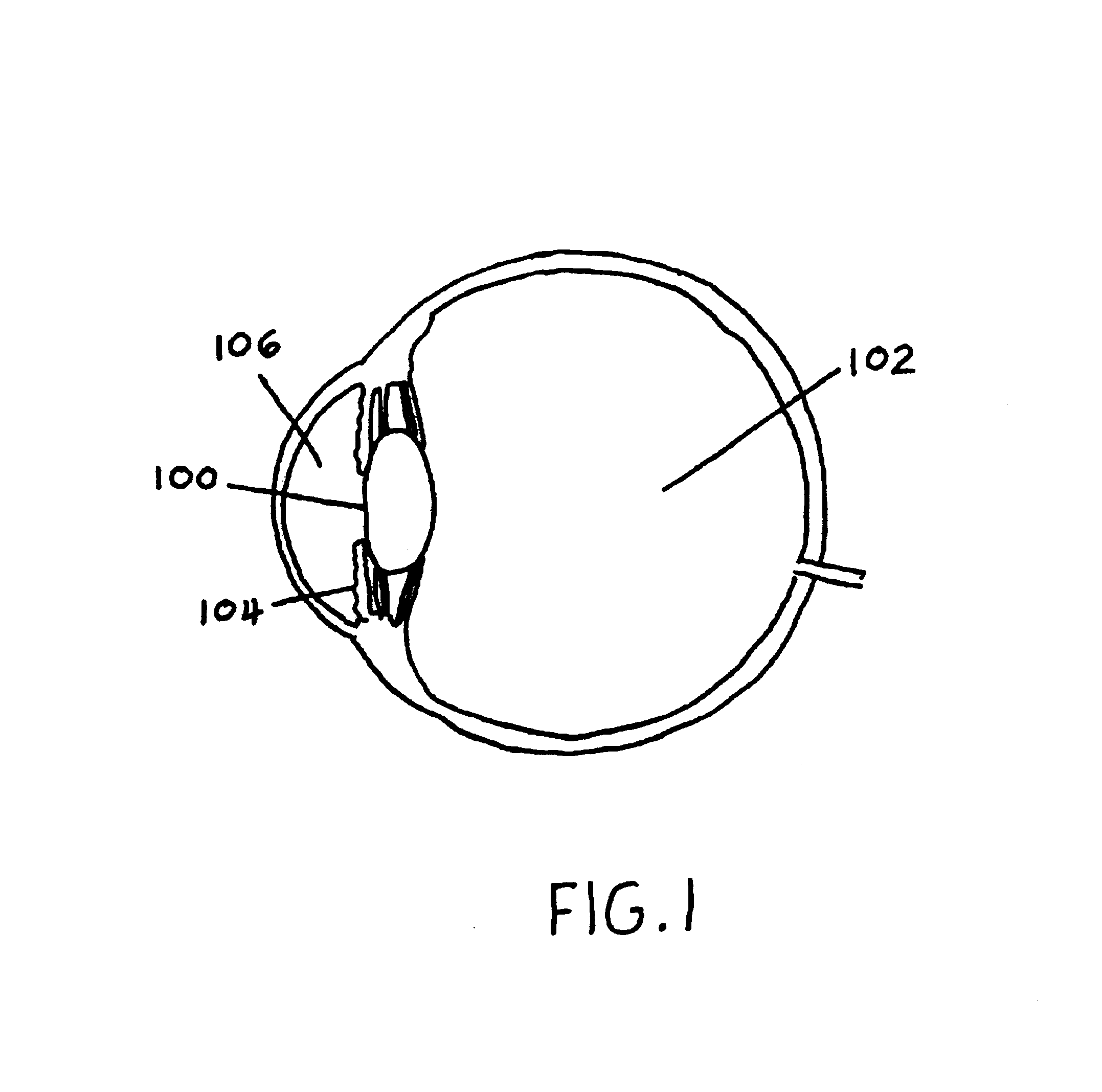
FIELD OF THE INVENTIONThe present invention relates to digital image processing, and more particularly to a method and apparatus for detecting and correcting red-eye defects in a digital image thereby reducing or eliminating the need for user intervention.BRIEF DESCRIPTION OF THE PRIOR ARTAs is well known, photographing a person in a relatively dark environment requires the use of a photographic flash to avoid under-exposure. However, a known artifact of such images is the appearance of a strong red circle instead of the eyes, also termed as “red-eye”. There are three main reasons for this artifact: 1) the proximity of the flash bulb to the lens; 2) the fact that if flash was needed, most likely the light was dim, and therefore the pupils of the eyes are naturally dilated. In addition, the physiology and anatomy of the eye, as illustrated in FIG. 1 plays an important role. 3) The fact that the eyes include a transparent lens 100 and medium 102 (Vitreous humor), and therefore light c...

Claims


Application Information

Patent Timeline
IPC IPC(8): G06K9/00G06T7/00G06T7/40H04N1/62
CPCG06K9/00228G06K9/00281G06K9/0061H04N1/624G06T7/004G06T7/408G06T7/0002G06T7/70G06T7/90G06V40/161G06V40/171G06V40/193
Inventor STEINBERG, ERAN
Owner LUMERO INC
Learn More