Temperature-independent arrayed waveguide grating device

a technology of arrayed waveguides and gratings, which is applied in the direction of optical waveguide light guides, instruments, optics, etc., can solve the problems of reducing the reliability of the overall system, increasing the system cost and the size of the device, and reducing the excess loss due to the groove inserted in the arrayed waveguide section of the arrayed waveguide grating. , to achieve the effect of reducing the loss and minimizing the loss

Inactive Publication Date: 2005-03-29
NEC CORP
View PDF12 Cites 3 Cited by
  • Summary
  • Abstract
  • Description
  • Claims
  • Application Information

AI Technical Summary

Benefits of technology

By the configuration including the sections, the excess loss due to the groove inserted in the arrayed waveguide section of t...

Problems solved by technology

This leads to a problem of variation in a filter transmission bandwidth (central wavelength) depending on ambient temperature.
This however increases the system cost and the size of the device, and reliability of the overall system is lowered.
However, it is difficult to manufacture, in one plane, waveguides respectively with different materials (particularly, in a planar lightwave circuit).
This leads to a problem of a complex and long production pr...

Method used


Image

  • Temperature-independent arrayed waveguide grating device
  • Temperature-independent arrayed waveguide grating device
  • Temperature-independent arrayed waveguide grating device

Examples


first embodiment

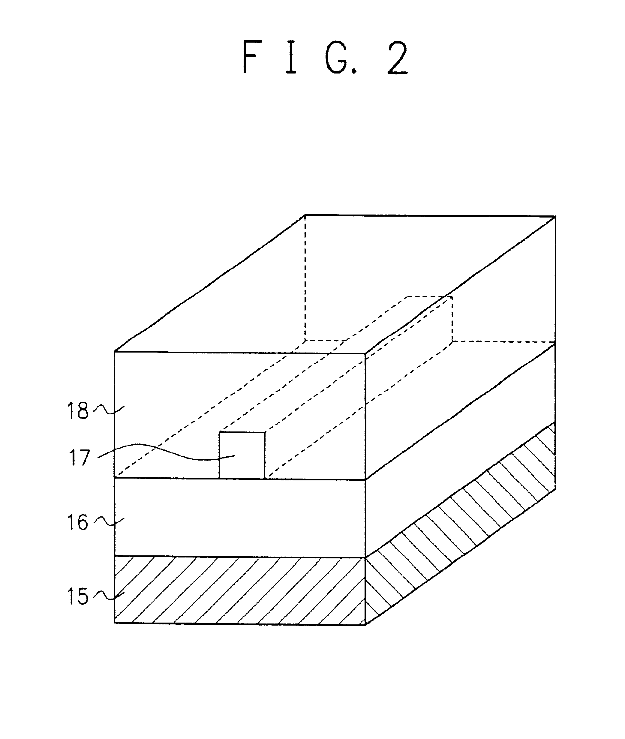
FIG. 3 shows a magnified view of an arrayed waveguide section of an arrayed waveguide grating in accordance with the present invention. The configuration of FIG. 3 includes arrayed waveguides (silica-based waveguides) 19, a wedge-shaped groove 20 formed in the waveguide section 19 to reach the substrate material 15 (i.e., the upper clad layer 18, the core region 17, and the lower clad layer 17 are accordingly removed), and photosensitive polymer 21 and 22 (having a negative refractive index temperature coefficient) filled in the groove 20.

When photosensitive polymer is filled in the groove 20, between the regions 21 and 22 they have no boundary, namely, they are equal to each other. In an operation to radiate a light beam onto the polymer to increase the value of refractive index, the region 22 has a high value of refractive index as a result. Conversely, in an operation to radiate a light beam onto the polymer to reduce the value of refractive index, the region 21 has a low value o...

second embodiment

FIG. 5 shows, in a magnified view, the arrayed waveguide section of the arrayed waveguide grating in accordance with the present invention. The configuration of FIG. 5 includes arrayed waveguide section 19 (including silica-based waveguides), a wedge-shaped groove 20 formed in the waveguide section 19 to reach a substrate, and polymer 38 filled in the groove 20, the polymer having a large value of refractive index and a negative refractive index temperature coefficient.

When light propagating through an optical waveguide enters a uniform medium, the light spreads as the light propagates therethrough if the medium does not include structure to confine the light.

Assume that the uniform medium has a refractive index of n, the propagating light has a spot size of w (the spot size is 1 / e at half-width (1 / e2 at half-width of power distribution) from a peak value when an electric-field distribution in a guided mode is fitted using Gaussian distribution), and a propagation constant of k (=2π...


PUM


Abstract

In an arrayed waveguide grating, a wedge-shaped groove formed in an arrayed waveguide section or a silica-based waveguide section in a periphery of the groove is modified in either one of the procedures below or in a particular combination thereof to suppress spreading of light in the groove to thereby reduce the excess loss due to addition of the groove. The material filled in the groove is a photosensitive material having a negative refractive index temperature coefficient. Using the photosensitivity, refractive index difference is provided in the groove to form optical waveguides in a horizontal direction or in vertical and horizontal directions. The material filled in the groove has a negative refractive index temperature coefficient to minimize a spreading angle of light incident to the groove. Width of each silica-based waveguide is enlarged before and after the groove to decrease the spreading angle of light incident to the groove. This method reduces the excess loss of the arrayed waveguide grating in which a wavelength characteristic is kept unchanged with respect to a change in ambient temperature.

Description

BACKGROUND OF THE INVENTIONThe present invention relates to a technology to reduce dependence of an arrayed waveguide grating (AWG) on temperature. In particular, the present invention relates to a technology in which by removing temperature dependence of a wavelength characteristic of an arrayed waveguide grating, external temperature compensation by a Peltier device or the like which has been indispensable to attain stable multiplexing and demultiplexing characteristics in an optical communication system in the prior art can be dispensed with.Prior ArtIn an optical fiber communication system, when dense wavelength division multiplexing (DWDM) is employed to increase transmission capacity, a multiplexer and / or demultiplexer (optical filter) is quite important to multiplex and to demultiplex wavelengths.Among various optical filters, an arrayed waveguide grating has a narrow-bandwidth wavelength characteristic and a high isolation ratio. The grating is a filter device of multiple in...

Claims


Application Information

Patent Timeline
IPC IPC(8): G02B6/10G02B6/34G02B6/12G02B6/293
CPCG02B6/10G02B6/12028G02B6/12011
Inventor YONEDA, SHIGERU
Owner NEC CORP
Why Eureka
Try Eureka