Timing skew compensation technique for parallel data channels

a timing skew and data channel technology, applied in pulse techniques, generating/distributing signals, instruments, etc., can solve the problems of increasing the speed of the bus, increasing the maximum timing skew, and increasing the problem of timing skew, so as to achieve the effect of substantially operating

Inactive Publication Date: 2005-03-29
MAXTOR
View PDF4 Cites 77 Cited by
  • Summary
  • Abstract
  • Description
  • Claims
  • Application Information

AI Technical Summary

Benefits of technology

[0014]The method and apparatus of the present invention can be implemented without substantial modifications to existing parallel data bus protocols (e.g. SCSI) and is contained within the receiver circuitry of the data bus. As such, the method and apparatus can operate substantially without requiring feedback to the transmitter. The apparatus of the present invention is particularly advantageous if implemented as a digital integrated circuit.

Problems solved by technology

This timing skew becomes more problematic as the data transmission rate of the data bus is increased.
Thus, in current SCSI implementations, the maximum timing skew is a fraction of the bit cell time, and is therefore only a minor problem.
However, the problem of timing skew becomes more pronounced as the speed of the bus is increased.
Consequently, time-skewed data bits in next-generation parallel data bus systems may be lost, thus reducing the reliability of the data bus.

Method used


Image

  • Timing skew compensation technique for parallel data channels
  • Timing skew compensation technique for parallel data channels
  • Timing skew compensation technique for parallel data channels

Examples


Embodiment Construction

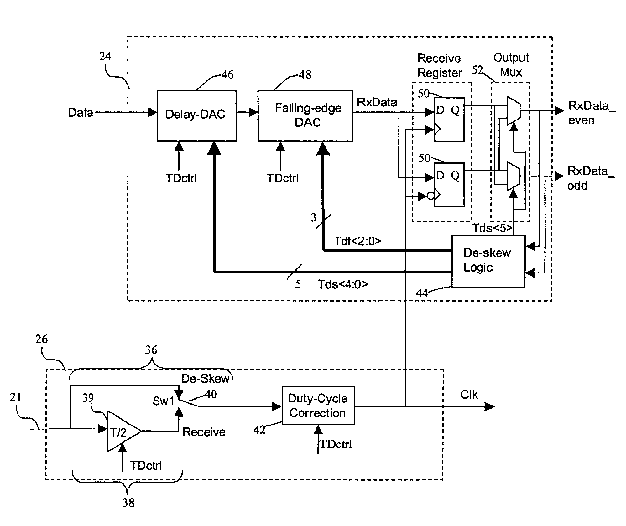
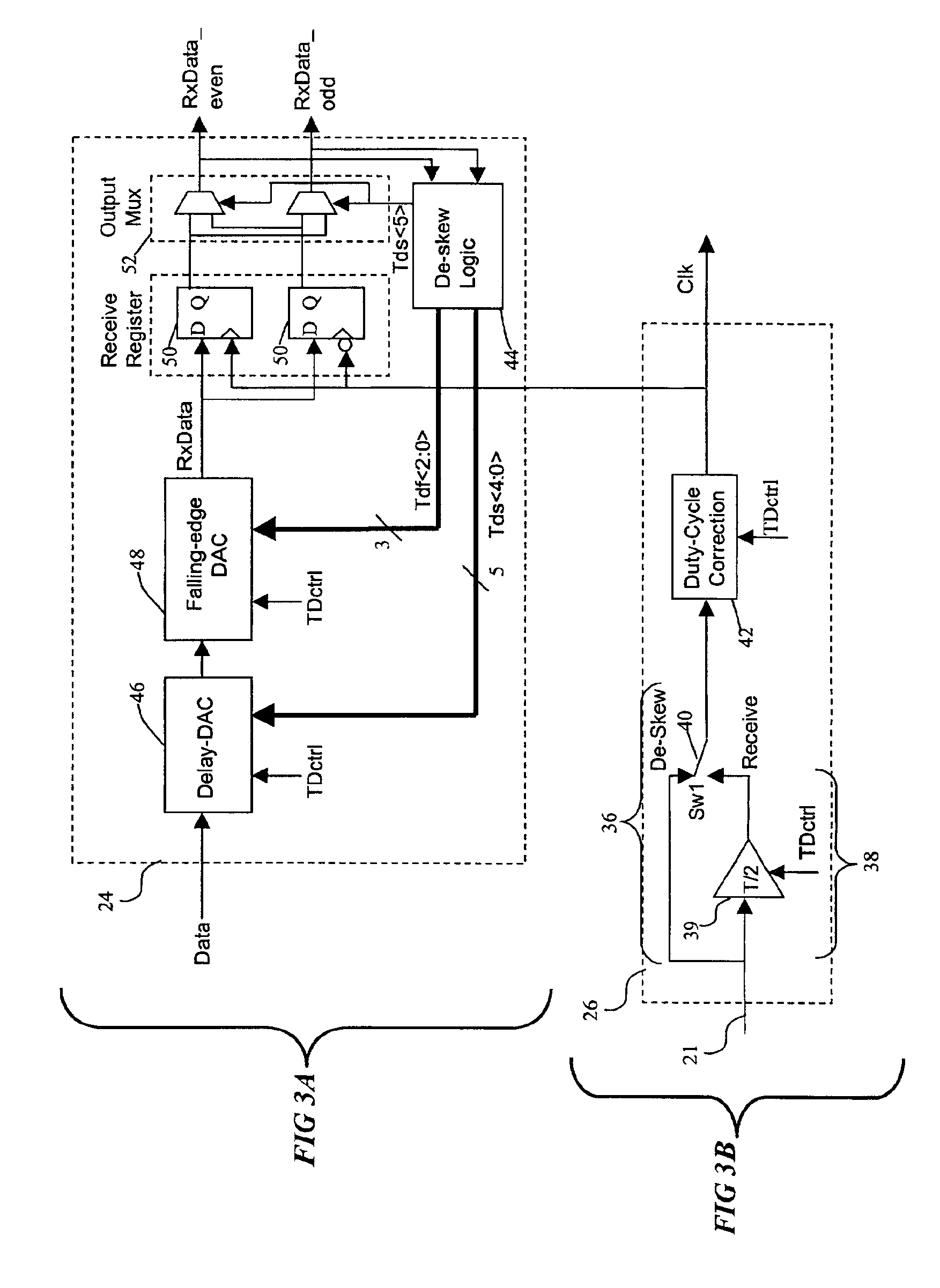
ting the various potential falling edge delay values using a falling edge DAC according to the present invention;

[0028]FIG. 9A is a comparative waveform illustration showing the potential effect of the falling edge DAC according to the present invention when data is early;

[0029]FIG. 9B is a comparative waveform illustration showing the potential effect of the falling edge DAC according to the present invention when data is late;

[0030]FIG. 10 is a schematic of a circuit implementation of a delay cell of the falling edge DAC of FIG. 7;

[0031]FIG. 11 is a flow chart diagram illustrating the blocks of a process according to the present invention.

DETAILED DESCRIPTION

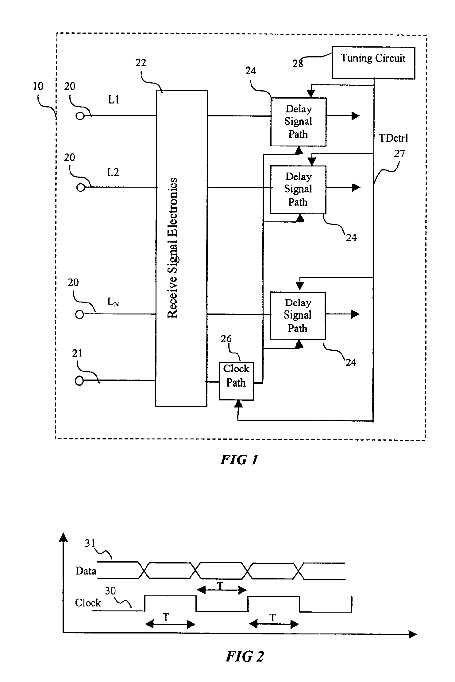
[0032]Referring now more particularly to the drawings, FIG. 1 is a schematic of the receive-side of a parallel data bus, indicated generally at 10. In this schematic, the data bus 10 consists of a plurality of individual data lines 20 (labeled L1-Ln) supplying data in parallel and a clock line 21. Each individual data line 20 ...


PUM


Abstract

A method and apparatus for correcting the timing skew of data signals in a parallel data transmission system, such as Small Computer System Interface (SCSI) data bus, relative to a receive clock in the data bus. The system separately corrects the receive clock duty cycle, and also features independent de-skewing of the rising and falling edges of a data waveform to improve timing accuracy of transmitted signals. The method and apparatus can be used without substantial changes to existing transmission system protocols, and can be implemented on an all-digital integrated circuit.

Description

BACKGROUND OF THE INVENTION[0002]1. Reservation of Copyright[0003]This patent document contains information subject to copyright protection. The copyright owner has no objection to the facsimile reproduction by anyone of the patent document or the patent, as it appears in the U.S. Patent and Trademark Office files or records, but otherwise reserves all copyright rights whatsoever.[0004]2. Field of the Invention[0005]The invention-relates generally to apparatus and methods for adjusting the timing of a data signal relative to a reference signal, and more specifically to an apparatus and method for de-skewing the timing of a data signal in a data transmission system having multiple parallel data channels.[0006]3. Description of Related Art[0007]Parallel data bus systems, such as Small Computer System Interface (SCSI) data bus systems, are widely used in personal computers. These systems are used to transmit data to and from computer peripherals, such as hard disk drives, and act as th...

Claims


Application Information

Patent Timeline
Patent Type & Authority Patents(United States)
IPC IPC(8): G06F1/10G06F1/12G06F5/06
CPCG06F1/10G06F1/12G06F5/06H03K5/133H03K5/135H03K2005/00058H03K2005/00104G06F2205/104
Inventor ALIAHMAD, MEHRANBROWN, RUSSELL WLESHAY, BRUCE
Owner MAXTOR
Why Eureka
Try Eureka