
Sensorless control induction motor rotor slot shapes and fabrication methods

a technology of induction motor and rotor, which is applied in the direction of rotors, synchronous motors, manufacturing cage rotors, etc., can solve the problems of not disclosing manufacturing methods or rotor designs, and achieve the effect of cost-effectiveness

Inactive Publication Date: 2005-04-05
GENERAL ELECTRIC CO
View PDF18 Cites 20 Cited by
  • Summary
  • Abstract
  • Description
  • Claims
  • Application Information

AI Technical Summary

Benefits of technology

It is therefore seen to be desirable to provide a cost effective method of creating spatial modulation. The present invention provides rotor lamination fabrication techniques to c

Problems solved by technology

Although large motors often have bar wound rotors with open slots, the majority of conventional small induction motors, however, are fabricated with closed rotor slots with the rotor bars being cost-effectively formed by casting molten aluminum (these rotors are usually machined and sometimes the bridges are removed and the slots are opened after casting).
U.S. Pat. No. 5,565,752 does not disclose manufacturing methods or rotor designs that are readily manufacturable with existing industrial casting processes and equipment.

Method used


Image

  • Sensorless control induction motor rotor slot shapes and fabrication methods
  • Sensorless control induction motor rotor slot shapes and fabrication methods
  • Sensorless control induction motor rotor slot shapes and fabrication methods

Examples


Embodiment Construction

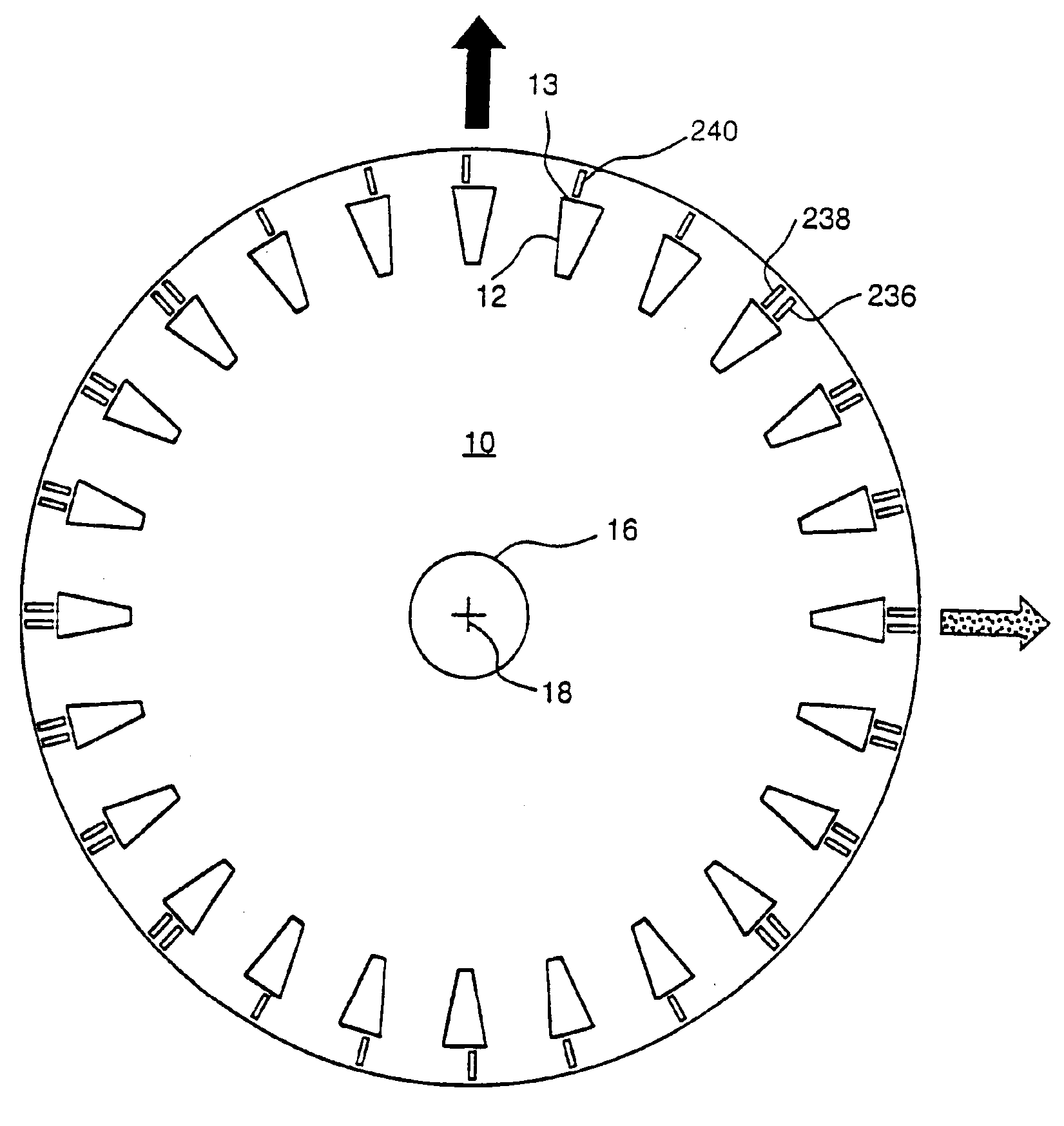
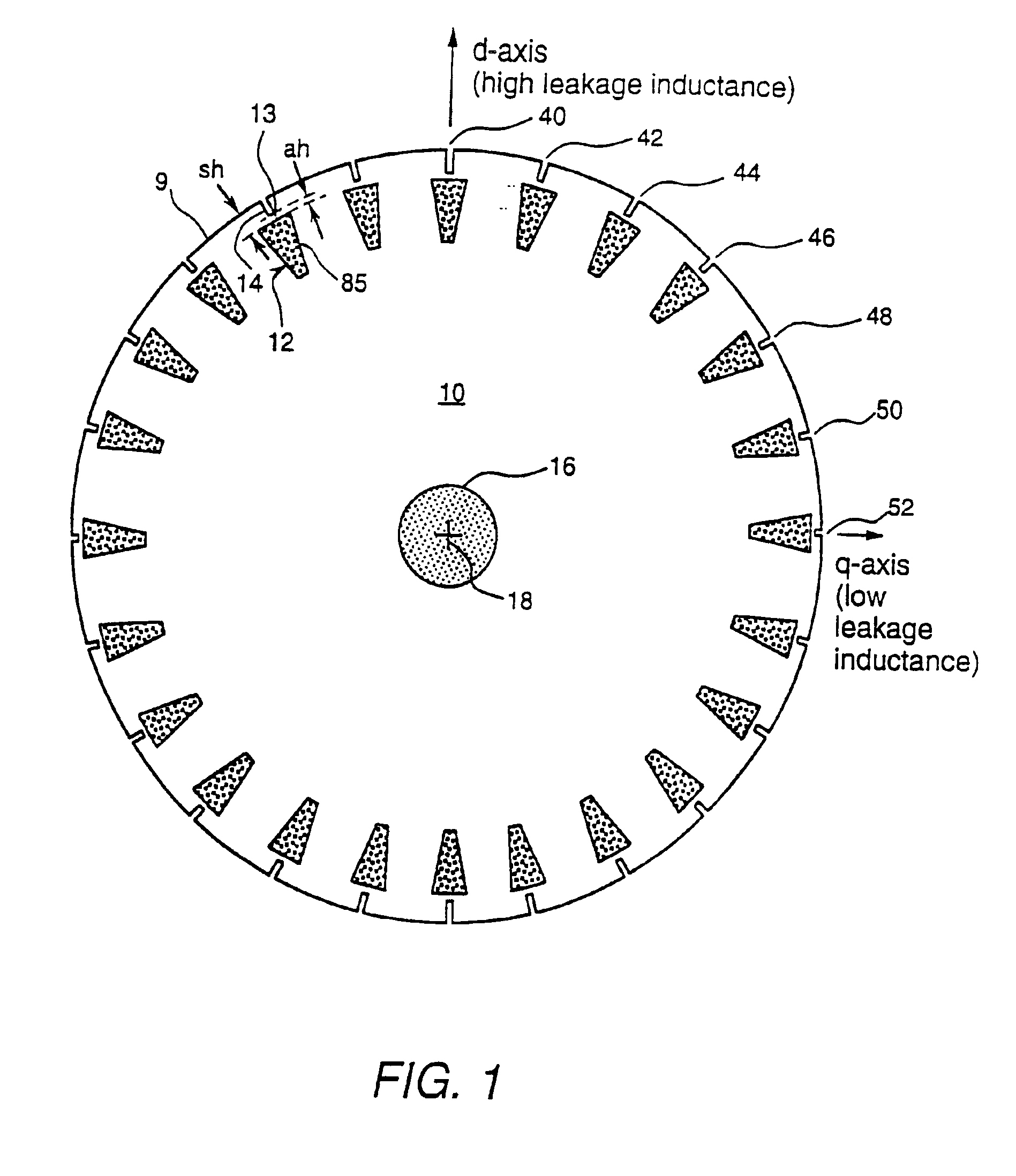
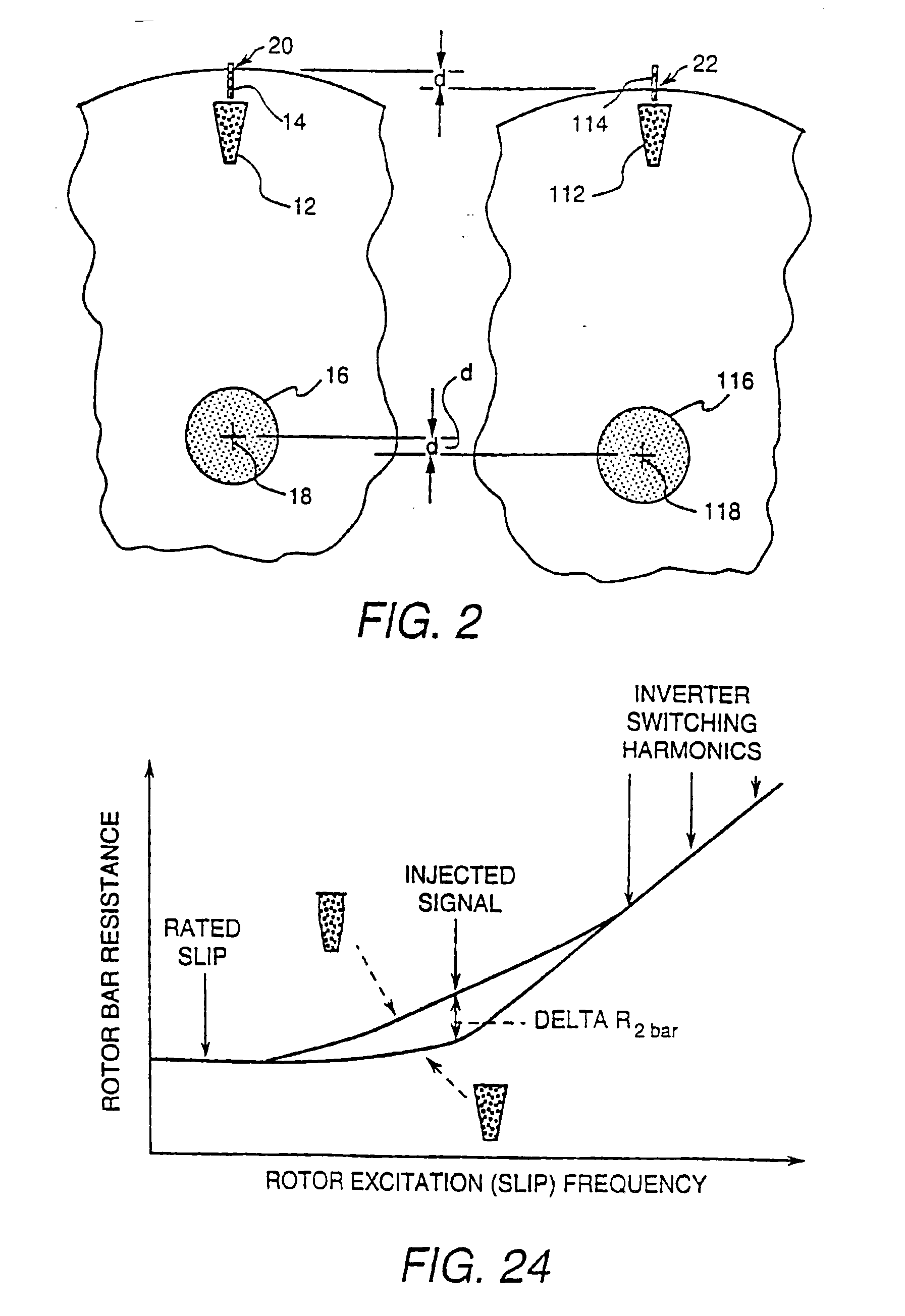
Some of the rotor slot shape and rotor bar embodiments of the present invention relate to inductance modulation, whereas others of the embodiments of the present invention relate to resistance modulation. Typically on larger machines (such as machines with greater than ten horsepower, for example), inductance modulation is most useful due to the fact that a high percentage of the total impedance results from inductance. On smaller machines (such as machines with less than ten horsepower, for example), inductance modulation, resistance modulation, or a combination of inductance modulation and resistance modulation can be useful for sensorless motor control. Preferably, for inductance modulation and particularly for resistance modulation, the cross sectional areas of each rotor slot shape are within one percent of each other such that the DC resistances of each bar are essentially identical. A spatial variation in the DC resistances will create undesirable torque ripple at the fundame...


PUM

PropertyMeasurementUnit
Timeaaaaaaaaaa
Diameteraaaaaaaaaa
Depthaaaaaaaaaa

Abstract

A method for fabricating an induction motor rotor lamination includes using an indexed notching die to punch a plurality of closed rotor slots at different distances from a center point of rotation by punching a first rotor slot, changing the position of a center point of the rotor lamination with respect to the notching die, and punching a second rotor slot. In another embodiment, a plurality of rotor slit patterns are punched using a variable depth indexed notching die including at least two rotor slit punching portions, one being deeper than another, by punching a first rotor slit pattern, changing the depth of closure of the notching die, and punching a second rotor slit pattern with the second rotor slit pattern having a different number of rotor slits than the first. In another embodiment, each rotor slit is open to and off center with respect to its respective rotor slot, and rotor laminations are stacked by positioning some of the rotor laminations in an orientation with is turned over and rotated with respect to others of the rotor laminations; filling the rotor slots and the rotor slits with cage material; and machining outer surfaces of the rotor laminations. In another embodiment, uniformly spaced identical rotor slots are punched and modulation is created by punching a contoured outside diameter or by inserting slot wedges of molded magnetic material.

Description

BACKGROUND OF THE INVENTIONClosed loop operation of induction motor drive systems without shaft transducers is commonly referred to as sensorless, tachless, or transducerless. Eliminating the need for rotor shaft transducers such as encoders, resolvers, and tachometers for position and velocity estimations in an induction motor drive system can reduce system cost, improve system reliability, and reduce the total motor package size.Several approaches for providing sensorless control of induction motors are described in U.S. Pat. Nos. 5,565,752 and 5,585,709 wherein a determinist spatial modulation in the rotor leakage inductance of the induction motor is tracked via the demodulation of an injected AC signal voltage or current. Tracking of the modulated rotor leakage inductance provides an estimate of the rotor position and velocity that can then be used for sensorless control.U.S. Pat. No. 5,565,752 describes induction motor rotors with spatial variations in the rotor leakage inducta...

Claims


Application Information

Patent Timeline
IPC IPC(8): B21D28/02B21D28/22H02K17/02H02K15/00H02K15/02H02K17/30H02K17/16
CPCB21D28/22B22D19/0054H02K15/0012H02K17/165H02K17/30H02K15/024Y10T29/49009Y10T29/49012H02K17/20H02K17/18
Inventor JANSEN, PATRICK LEEWEISSNER, STEVEN WELLS
Owner GENERAL ELECTRIC CO
Learn More