
Throttle valve control device

a control device and throttle valve technology, applied in the direction of electric control, speed sensing governor, machine/engine, etc., can solve the problems of large fluctuations in the torque of the throttle valve shaft itself, no energy source for returning the throttle valve, and extreme undesirable effects, so as to prevent misjudgment of breakage failure, good precision, and good precision

Active Publication Date: 2005-04-05
MITSUBISHI ELECTRIC CORP
View PDF6 Cites 20 Cited by
  • Summary
  • Abstract
  • Description
  • Claims
  • Application Information

AI Technical Summary

Benefits of technology

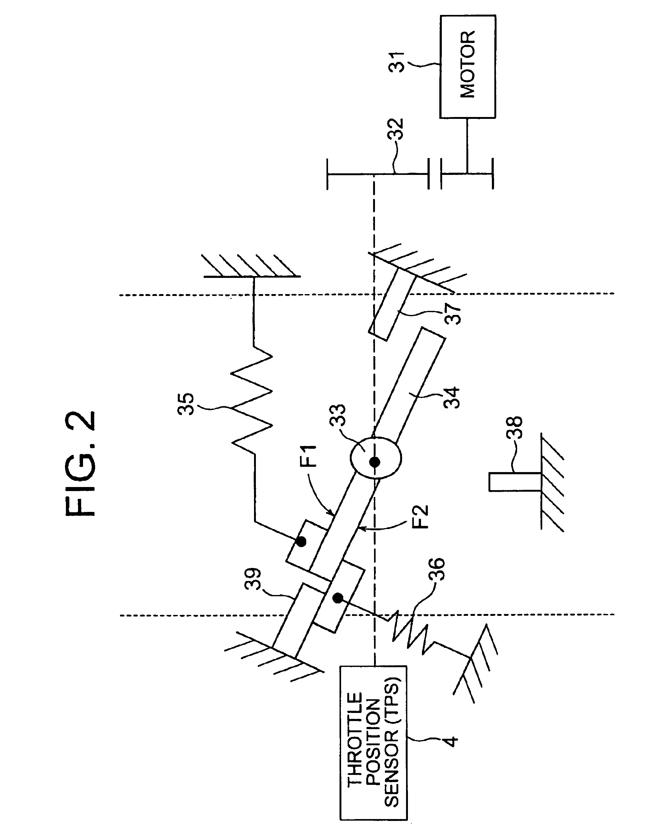
The present invention provides a throttle valve control device that can accurately detect the breakage of the return spring of a throttle valve. This is achieved by driving the motor to a predetermined opening degree position and then cutting off power to the motor. The device then checks the output value of the throttle position sensor after a set period of time. If there is no significant change in the output value, the device concludes that there is a breakage failure in the return spring. This prevents misjudgments and ensures precise detection of breakage to the return spring.

Problems solved by technology

An engine driving force may develop against the intention of the driver, which is extremely undesirable.
Conversely, if there is an abnormality in an electric system of the DC motor, such as a breaking of wires of the DC motor terminals, while the driver presses the accelerator into a fully opened state, there is no energy sources for returning the throttle valve even if the accelerator pedal is returned to a fully closed position.
As a result, the throttle valve stays in the fully opened position, and an engine driving force may develop against the intention of the driver, which is extremely undesirable.
However, there are large fluctuations in the torque of a throttle valve shaft itself during engine operation, such as: changes in torque constant of the DC motor due to individual differences in the torque characteristics of the throttle shaft of the throttle actuator and temperature changes (reduction in magnet force of permanent magnetism); changes in viscous resistance of a lubricant in a speed reduction gear portion; transient contaminants that engage in between a valve and a bore; and changes over time in an amount of adhered sludge.
As a result, misjudgments tend to occur for the above-mentioned cases.
In addition, there occurred such problems that the detection precision became worse, etc. when the given value used in the judgments is made larger in order to avoid the misjudgments.

Method used


Image

  • Throttle valve control device
  • Throttle valve control device
  • Throttle valve control device

Examples


Embodiment Construction

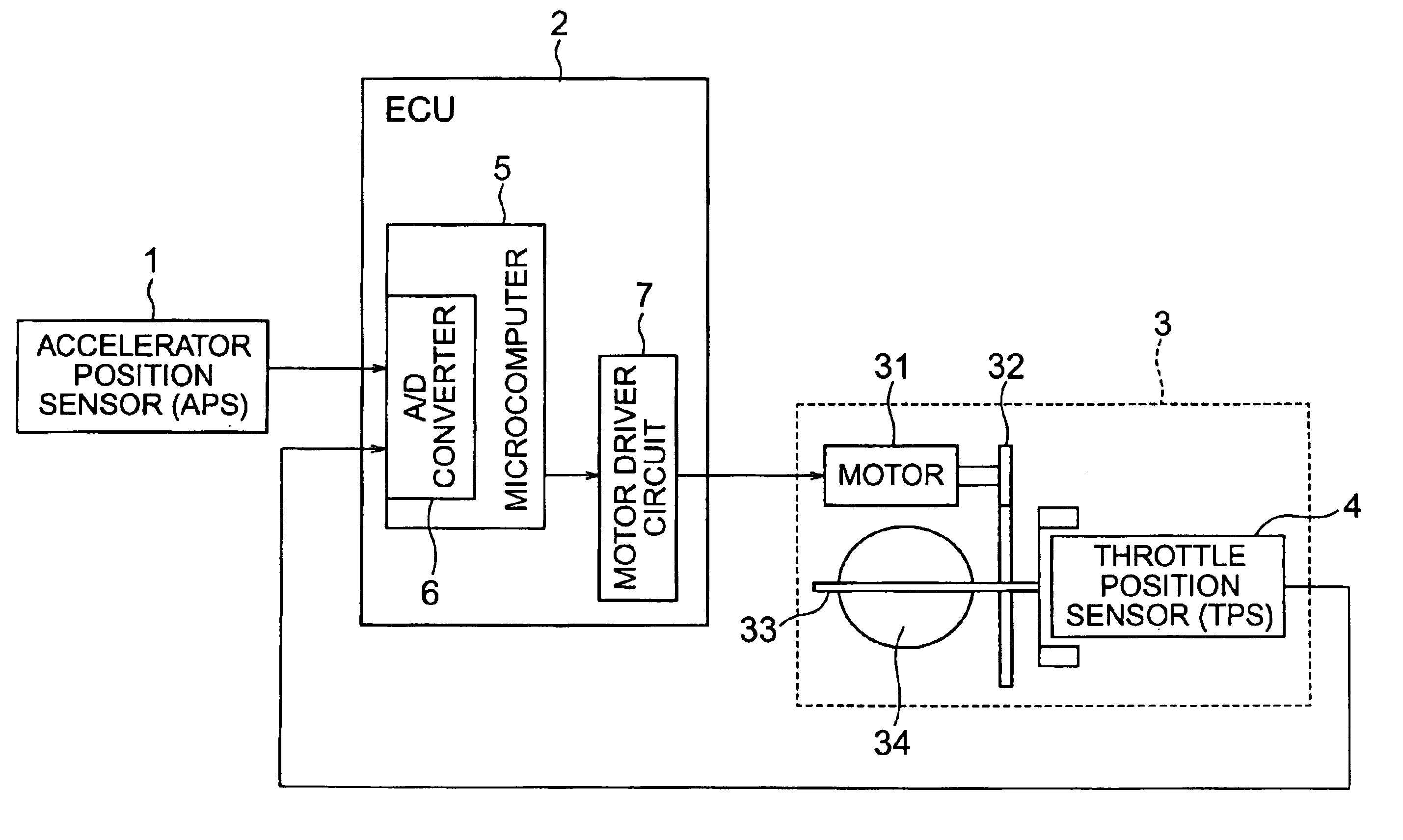
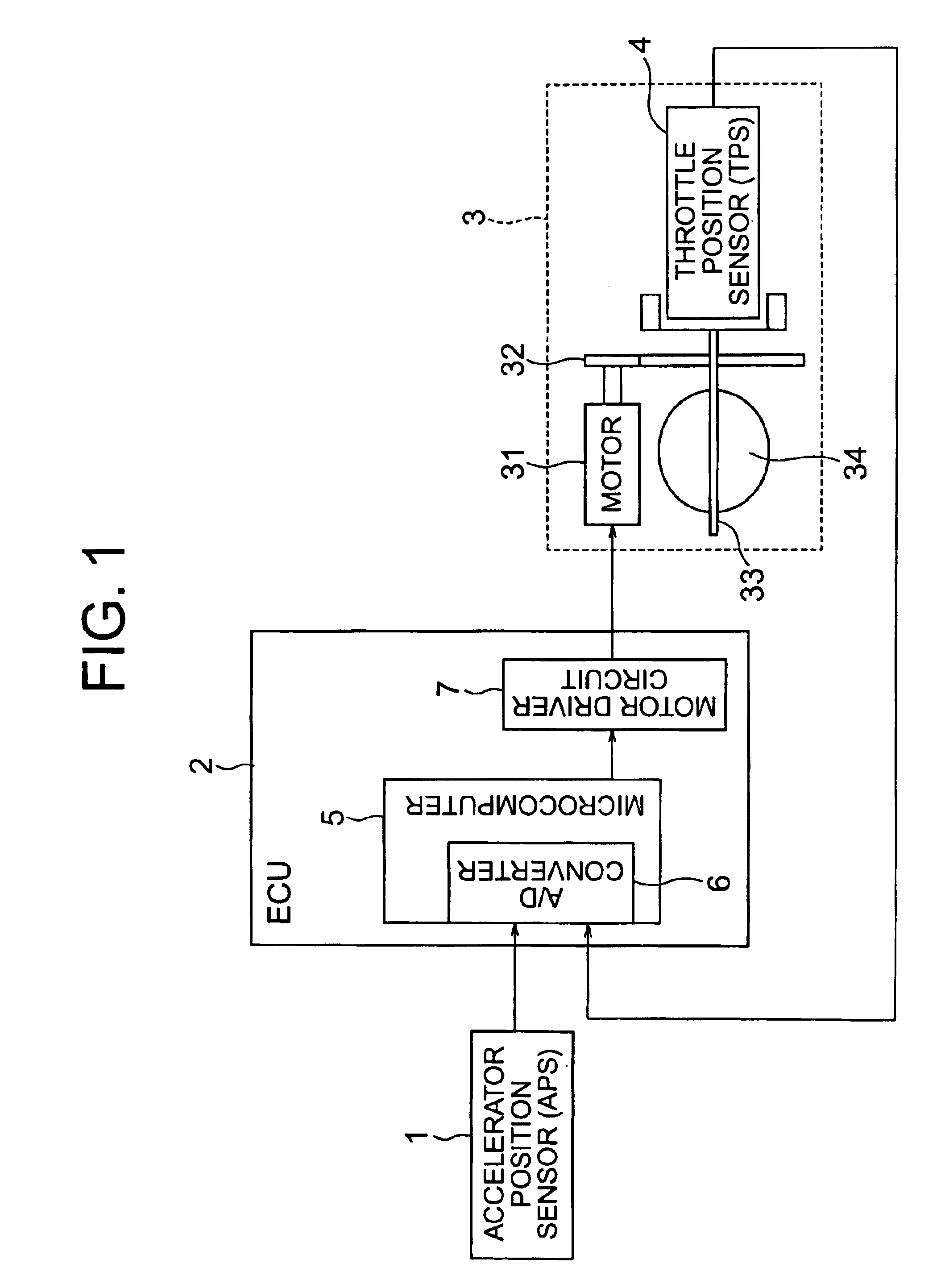
An embodiment of the present invention is explained below. FIG. 1 is a schematic structural view for showing a configuration of a throttle valve control device according to an embodiment of the present invention, the control device controlling an amount of air intake of an engine. As shown in FIG. 1, an ECU 2 is connected to an accelerator position sensor (APS) 1, and a throttle actuator 3 is connected to the ECU 2. The accelerator position sensor 1 is a sensor that detects the position of an accelerator pedal as an accelerator opening degree. Further, the ECU 2 is an electronic control unit that performs various types of engine control, and includes a throttle control means (not shown) that performs control of the amount of air intake of the engine. As shown in FIG. 1, the ECU 2 has a microcomputer 5, a DC motor driver circuit 7, and the like. An A / D converter 6 is provided in the microcomputer 5 in order to perform A / D conversion of an accelerator opening degree signal from the ac...


PUM


Abstract

An ECU 2 performs ON / OFF judgments on an ignition switch. When the ignition switch is OFF, a judgment is made whether or not voltage learning for a fully opened position of a throttle valve 34 is complete. If complete, an electric power for a DC motor 31 is cutoff. A TPS output voltage value is read in, and a judgment is made whether or not a given period of time has elapsed. If the given period of time has elapsed, and if a throttle position sensor output voltage value VTPS is equal to or greater than a given value, then a judgment is made that there is a return spring 35 breakage failure. Breakage to the return spring 35 can thus be reliably detected.

Description

BACKGROUND OF THE INVENTION1. Field of the InventionThe present invention relates to a throttle valve control device. In particular, the present invention relates to a throttle valve control device that detects an amount of opening degree of a throttle valve, which is provided within an intake pipe of an engine used in an automobile, to perform feedback control of the throttle valve to a position having a desired opening degree by using a throttle actuator.2. Description of the Related ArtIn a conventional throttle abnormality detection device in an internal combustion engine, for detecting return spring abnormalities of a throttle actuator, a throttle controlling means controls an opening degree of the throttle valve using a DC motor based on an amount that an accelerator pedal is pressed. Actual torque that the motor generates is detected by a torque detecting means, and an amount of fluctuation in the torque is detected for every given period of time by a fluctuation amount detec...

Claims


Application Information

Patent Timeline
Patent Type & Authority Patents(United States)
IPC IPC(8): F02D11/10F02D41/04F02D9/02F02D41/14F02D41/22F02D45/00
CPCF02D11/107F02D2250/16F02D41/042
Inventor WATANABE, SHINJI
Owner MITSUBISHI ELECTRIC CORP
Learn More