Micropipette and dispenser

a dispenser and micropipette technology, applied in the field of micropipette, can solve the problems of reducing the use efficiency and shortening the channel, and achieve the effects of preventing the trouble of a spotting position being shifted or a spot mixing, and facilitating the replacement of locally-defective pip

Inactive Publication Date: 2005-04-05
NGK INSULATORS LTD
View PDF26 Cites 15 Cited by
  • Summary
  • Abstract
  • Description
  • Claims
  • Application Information

AI Technical Summary

Benefits of technology

Because a micropipette of the present invention uses the above structure, a very small amount of a liquid is expelled through an injection port corresponding to each time a piezoelectric / electrostrictive element is driven and the volume of the liquid is very small and constant. The driving cycle can correspond to a high frequency by using the piezoelectric / electrostrictive element, and the time required for injection is also decreased. Moreover, because a sample moves in a closed space before the sample is expelled after it is delivered, the sample is not dried during that period. Furthermore, because the substrate can be compactly formed, it is possible to shorten the channel through which a sample moves and reduce the deterioration of use efficiency due to the attachment of the sample to the channel wall.
Moreover, it is preferable that each of the dispensers has a different-directional-flying-droplet shielding plate made of a thin plate having a hole coaxial with an injection port outside the injection port. Thus, even if the expelling direction of an injection droplet is deviated, the droplet does not reach a substrate. Therefore, it is possible to prevent that the troubles of a spotting position being shifted or a spot mixing with an adjacent spot.

Problems solved by technology

Furthermore, because the substrate can be compactly formed, it is possible to shorten the channel through which a sample moves and reduce the deterioration of use efficiency due to the attachment of the sample to the channel wall.

Method used


Image

  • Micropipette and dispenser
  • Micropipette and dispenser
  • Micropipette and dispenser

Examples


Embodiment Construction

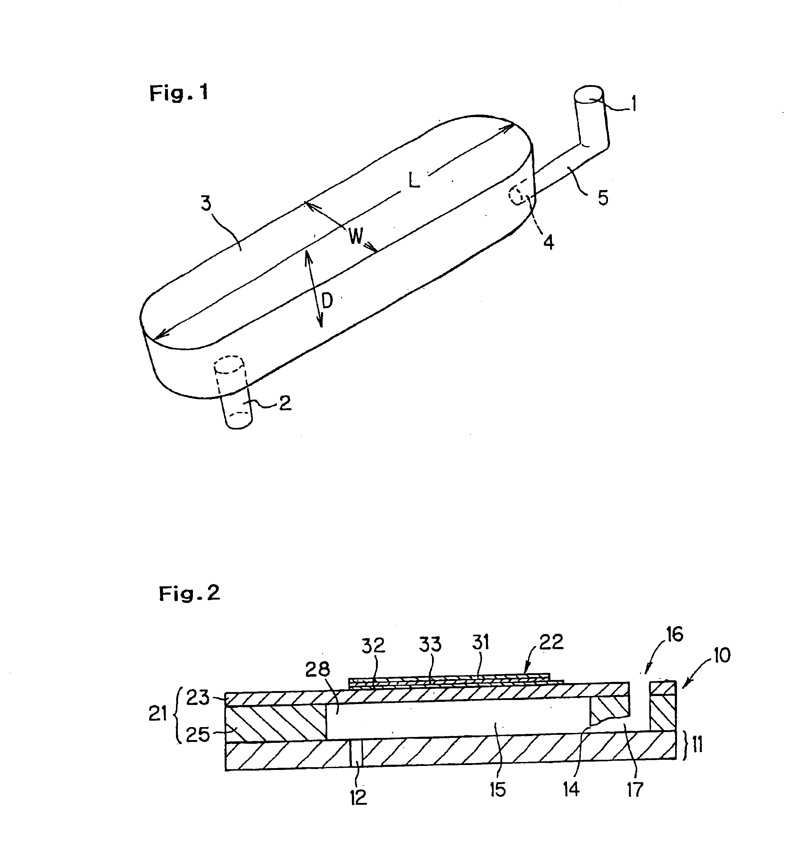
According to the basic structure of a micropipette of the present invention, a sample inlet port, a cavity to be filled with a sample, and a sample injection port are formed on at least one substrate, and a piezoelectric element is provided for at least one wall surface forming the cavity of the substrate. Moreover, the micropipette preferably has a structure that the sample moves as a laminar flow in the cavity. A micropipette having such a structure is able to efficiently form a microspot on a substrate or slide, such as a DNA chip, at a high accuracy and a high speed by changing volumes in a cavity in accordance with the driving of a piezoelectric / electrostrictive element and expelling a certain amount of a sample in the cavity through an injection port.

The present invention will be described below in detail in accordance with the embodiments shown in the accompanying drawings. However, the present invention is not restricted to the embodiments.

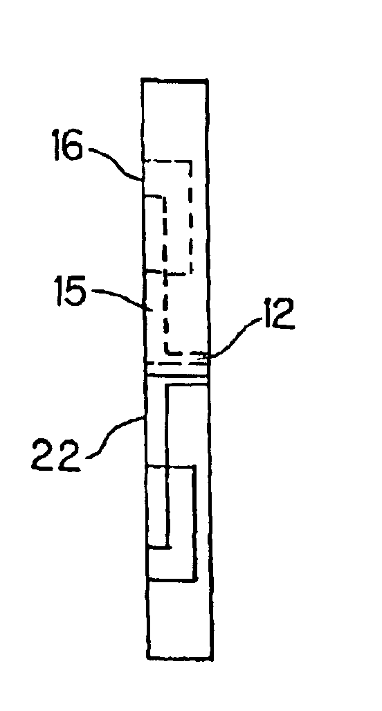
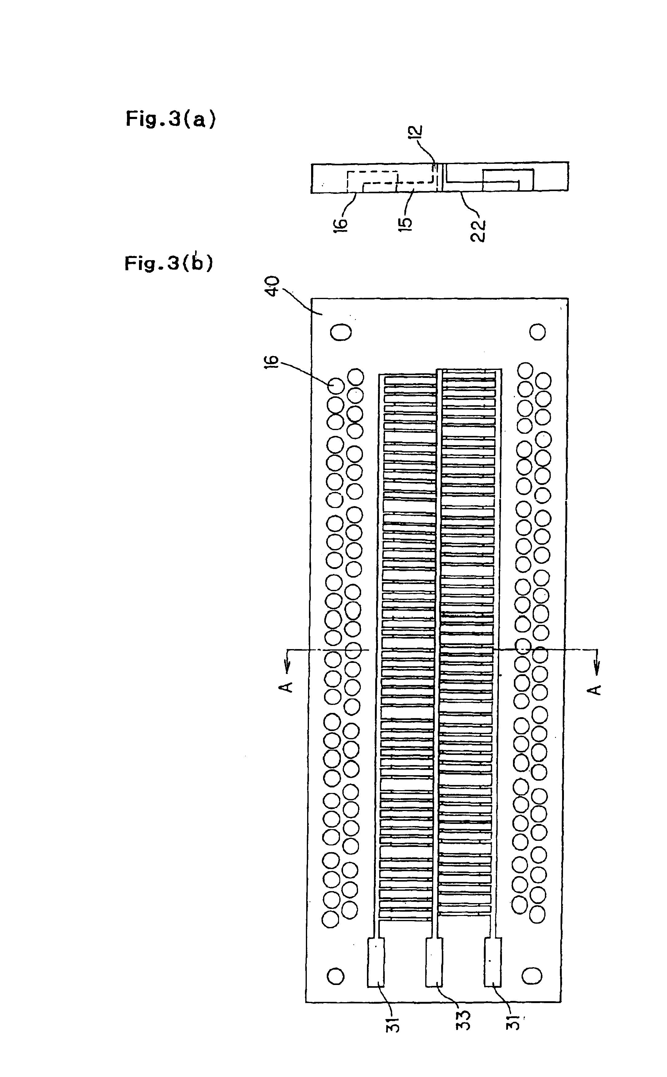
FIG. 2 shows a micropipette of the ...


PUM

PropertyMeasurementUnit
depthaaaaaaaaaa
widthaaaaaaaaaa
lengthaaaaaaaaaa

Abstract

A micropipette constructed for dispensing sequential, different sample solutions, including a substrate, an inlet port formed in or on the substrate, a cavity into which the sample solutions are poured through the inlet port and which is filled sequentially with the sample solutions, an introduction hole between each inlet port and cavity, an injection port for sequentially expelling the sample solutions formed in communication with each cavity, and a piezoelectric / electrostrictive element provided on at least one wall of the substrate adjacent each cavity.

Description

BACKGROUND OF THE INVENTION AND RELATED ART STATEMENTThe present invention relates to a micropipette superior in droplet-volume controllability and productivity and preferably used to line and fix micro-volume droplets at a high density for applications such as manufacturing of DNA chips. The present invention further relates to a dispenser using the micropipette.The genetic-structure analyzing method has been remarkably advancing recently, and many genetic structures, including structures of human genes, have been clarified. To analyze the above genetic structures, a DNA chip is used in which thousands to tens of thousands or more of different types of DNA pieces are lined and fixed as microspots on a substrate, such as a microscope slide glass.As methods for forming microspots in manufacturing the DNA chip, the QUILL method, the pin-and-ring method, and the spring pin method are widely used. Even when any method is used, it is necessary to decrease the fluctuation of volumes and s...

Claims


Application Information

Patent Timeline
Patent Type & Authority Patents(United States)
IPC IPC(8): B01L3/00B01L3/02B01L7/00B01J19/00C12Q1/68G01N35/00G01N35/10B01L9/00C40B40/06C40B60/14
CPCB01J19/0046B01L3/0268B01L3/5085B01L3/5088C12Q1/6837G01N35/00029Y10T436/25B01J2219/00351B01J2219/00369B01J2219/00378B01J2219/00527B01J2219/00529B01J2219/00585B01J2219/0059B01J2219/00596B01J2219/00605B01J2219/00608B01J2219/00612B01J2219/00637B01J2219/00659B01J2219/00722B01L3/0241B01L9/54B01L2200/021B01L2200/027B01L2300/0816B01L2300/0819B01L2400/027B01L2400/0439C40B40/06C40B60/14G01N2035/00158G01N2035/1039B01J2219/00317Y10T436/2575C12Q2565/507
Inventor HIROTA, TOSHIKAZUTAKAHASHI, NOBUOTAKEUCHI, YUKIHASA
Owner NGK INSULATORS LTD
Why Eureka
Try Eureka