Spindle mounted telemetry system

a telemetry system and spindle technology, applied in vehicle tyre testing, instruments, roads, etc., can solve the problems of system not easily adapted to other wheels or environments, problems such as interference between rotating rim components, and high price of custom rims, so as to simplify the anti-rotation attachment, minimize the protrusion, and facilitate the effect of mounting

Inactive Publication Date: 2005-04-05
MTS SYSTEMS CORPORATION
View PDF8 Cites 4 Cited by
  • Summary
  • Abstract
  • Description
  • Claims
  • Application Information

AI Technical Summary

Benefits of technology

In one embodiment, the telemetry assembly can be used in a telemetry system that includes a hub adapter mountable to the spindle and a transducer mountable to the hub adapter. Housings may be provided in order to support the wireless transmitter and the receiving antenna. The housings may be annular in design and include a central aperture so as to allow the telemetry assembly to be placed concentrically with the existing spindle bearings, thus allowing the location of the telemetry system to be maintained inboard of the wheel assembly wherein at least one of the spindle or a non-rotating member of the spindle extends through the central aperture and thus simplify the antirotate attachment and minimize the protrusion from the face of the spindle.
The telemetry assembly is easily mountable to various types of spindles. A stator housing of the telemetry assembly is mountable to a non-rotating element of the spindle. An antirotate connection assembly secures the stator housing to the non-rotating element. The stator housing can be disposed between the connection assembly and a rotor housing.
The guiding system provides for independent control of the position and rotation of the rotor relative to the stator, thus eliminating the dependency on spindle bearing accuracy, and / or manual alignment of other separate telemetry components such as electronic-embedded rims and stationary receivers, to maintain the relative positions of the rotor and stator portions of the telemetry system. A central aperture is provided in the guiding system to allow the spindle or rotating members coupled to the spindle to extend therethrough.
The housings provide a compact, modular, self-guided assembly that is easily mountable to various types of spindles. In particular, the housings are particularly useful in mounting to various vehicles, including different types of automobiles. If desired, an angular positioning device and a wireless power coupling can be used with or incorporated within the telemetry system.

Problems solved by technology

Accordingly, the slip ring assembly thus projects outwardly from the wheel, which is undesirable since the projection may contact obstacles.
The custom rims are expensive and require alignment of a stationary pick-up device during installation.
In addition, the runout of a rim and / or spindle bearings, and / or deformation of the rim under loading can create problems and interferences between the rotating rim components, and the stationary suspension or vehicle mounted components due to varying gap between the stationary body and the rotating body.
An anti-rotate device must again wrap around the wheel to an attachment point behind the wheel, thereby having the disadvantages discussed above with the slip ring assembly.
In addition, these systems are not easily adapted to other wheels or environments.

Method used


Image

  • Spindle mounted telemetry system
  • Spindle mounted telemetry system
  • Spindle mounted telemetry system

Examples


Embodiment Construction

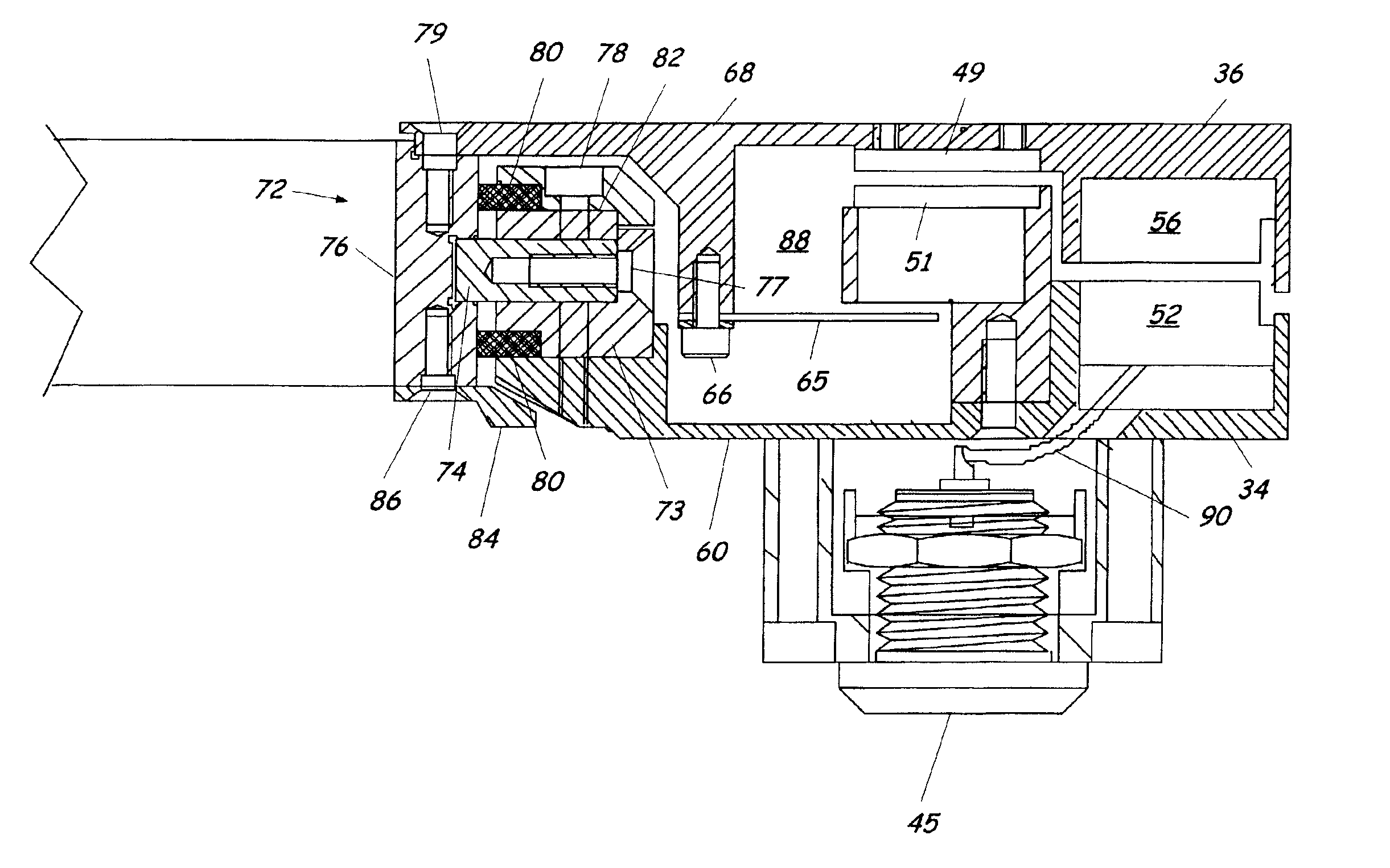
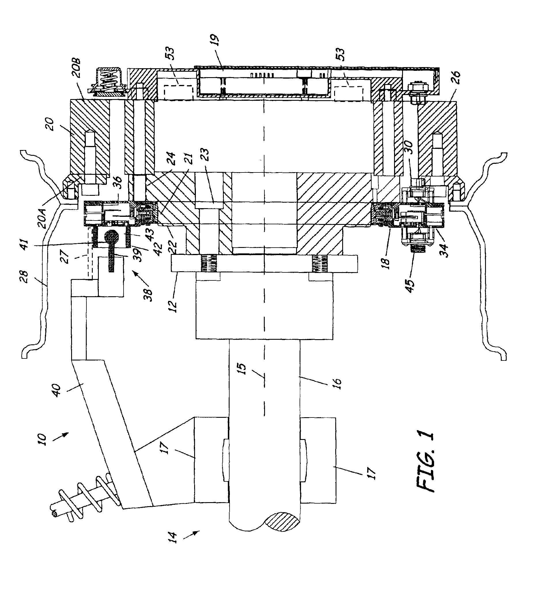
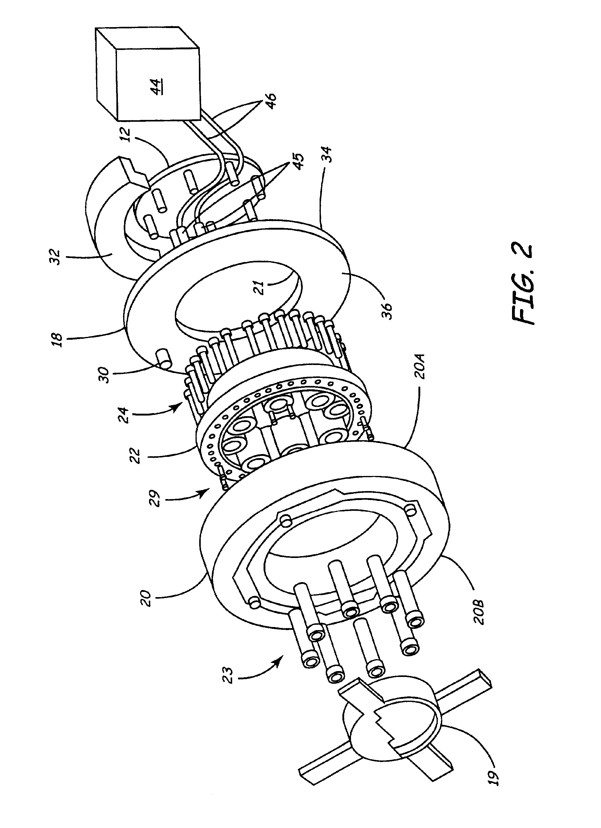
Referring to FIG. 1, a telemetry system 10 includes a telemetry assembly 18 and transducer 20 that are mountable to a hub 12 of a spindle 14 (herein by example a vehicle spindle). Spindle 14 has a spindle axis 15 about which rotating elements rotate relative to non-rotating elements. Hub 12 is connected to a shaft 16 that rotates on vehicle spindle bearings 17, schematically illustrated. Generally, the telemetry system 10 includes the telemetry assembly 18 and optional hub electronics 19. The telemetry assembly 18 is couplable to a transducer 20 (herein a force transducer) that measures forces and loads upon the vehicle spindle 14, although other forms of transducers such as displacement, acceleration, temperature and pressure transducers mounted to the vehicle spindle 14 can also be used. The telemetry assembly 18 can be disposed on a side 20A of the transducer 20 facing the hub 12 to form a compact system with minimal projection from the vehicle spindle.

Referring also to FIG. 2, t...


PUM


Abstract

The present invention relates to a telemetry assembly for a spindle. The telemetry assembly includes a wireless transmitter coupled to the spindle to rotate therewith and a receiving antenna wirelessly coupled to the transmitter. A guiding system having a central aperture and coupled to the wireless transmitter and the receiving antenna guides rotation of the wireless transmitter relative to the receiving antenna. If desired, the telemetry assembly can be used in a telemetry system including a hub adapter mountable to the spindle and a transducer mountable to the hub adapter. Furthermore, an angular positioning device and a wireless power coupling can be provided.

Description

BACKGROUND OF THE INVENTIONThe present invention relates to a transducer mounted to a spindle. More particularly, the present invention relates to a telemetry system that transmits signals from the rotating transducer to a stationary body.A common system for transmitting signals from a rotating transducer to a stationary member is by using a contacting slip ring. In vehicle spindle mounted applications, the slip ring, as well as an optional angular encoder, require an anti-rotate connection to a non-spinning portion of the vehicle. Most slip rings also require that the slip ring tracks and brushes be located on a small radius around the axis of rotation for the purposes of decreasing the surface speed of the brushes in the slip ring assembly. Typically, this requires that the slip ring assembly be placed outboard of the vehicle wheel assembly on the axis of rotation. The antirotate connection wraps around the outside of the wheel assembly to attach on the inside of the wheel at the ...

Claims


Application Information

Patent Timeline
Patent Type & Authority Patents(United States)
IPC IPC(8): G08C19/38B60B35/18B60C23/02G08C17/02G01D5/245
CPCG08C19/38
Inventor SOMMERFELD, JODI L.MEYER, RICHARD A.LARSON, BRETT A.OLSON, DOUGLAS J.
Owner MTS SYSTEMS CORPORATION
Why Eureka
Try Eureka