Amplitude and phase-controlled antennas-subsystem

a phase control and antenna subsystem technology, applied in the direction of antennas, reradiation, transmission, etc., can solve the problems of low space available for the accommodation of the radar system, the rf performance suffers on a large amount of rf losses and electrical and mechanical interfaces, and the access from the rear is often impossible or only possible, so as to improve the noise level, reduce the space requirement, and improve the effect of heat removal

Inactive Publication Date: 2005-04-05
AIRBUS DEFENCE & SPACE
View PDF7 Cites 18 Cited by
  • Summary
  • Abstract
  • Description
  • Claims
  • Application Information

AI Technical Summary

Benefits of technology

It is an objective of the present invention to provide a radar system of the above-mentioned type that requires little volume whereas the transmit / receive modules are easily interchangeable for maintenance and repair work.
An essential advantage of the radar system of the invention is that an exchange of the transmit / receive module can take place from the irradiation side or front side of the radar system, which is very advantageous for many applications. It is another advantage of the radar system of the present invention that the antenna array can be adjusted to a curved surface when a structure-integrated antenna or conformal antenna is desired. Another advantage of the radar system of the present invention are the reduced number of RF interfaces and use of short high frequency lines to the antenna and therefore a low noise figure, lower high frequency losses and a low signal coupling. Finally, it is an advantage of the radar system of the present invention that a simple construction of the data and supply network is possible.
According to another advantageous embodiment, a first substrate is arranged on the side of the transmit / receive module facing the data and supply network which carries a high frequency power amplifier of the transmitter and receiver circuit to improve heat removal.
According to yet another advantageous embodiment, a second substrate is installed on the side of the transmit / receive module facing away from the data and supply network, and the circulator circuit carries the antenna element, as well as parts of the transmitter and receiver circuit. This makes possible a reduction of the space requirement, as well as an optimization of the noise level.

Problems solved by technology

Therefore, their RF performance suffers on a high amount of RF losses and electrical and mechanical interfaces.
One difficulty exists in many application areas of radar and ECM systems (ECM=Electronic Counter Measures) with active phase controlled antenna arrays, e.g., for airplanes: There is very little space available for the accommodation of the radar system, and access from the rear is often impossible or only possible under difficult circumstances.
Other substrate materials could also be used, but reduced performance (e.g. loss, thermal resistance) will be possible.

Method used


Image

  • Amplitude and phase-controlled antennas-subsystem
  • Amplitude and phase-controlled antennas-subsystem
  • Amplitude and phase-controlled antennas-subsystem

Examples


Embodiment Construction

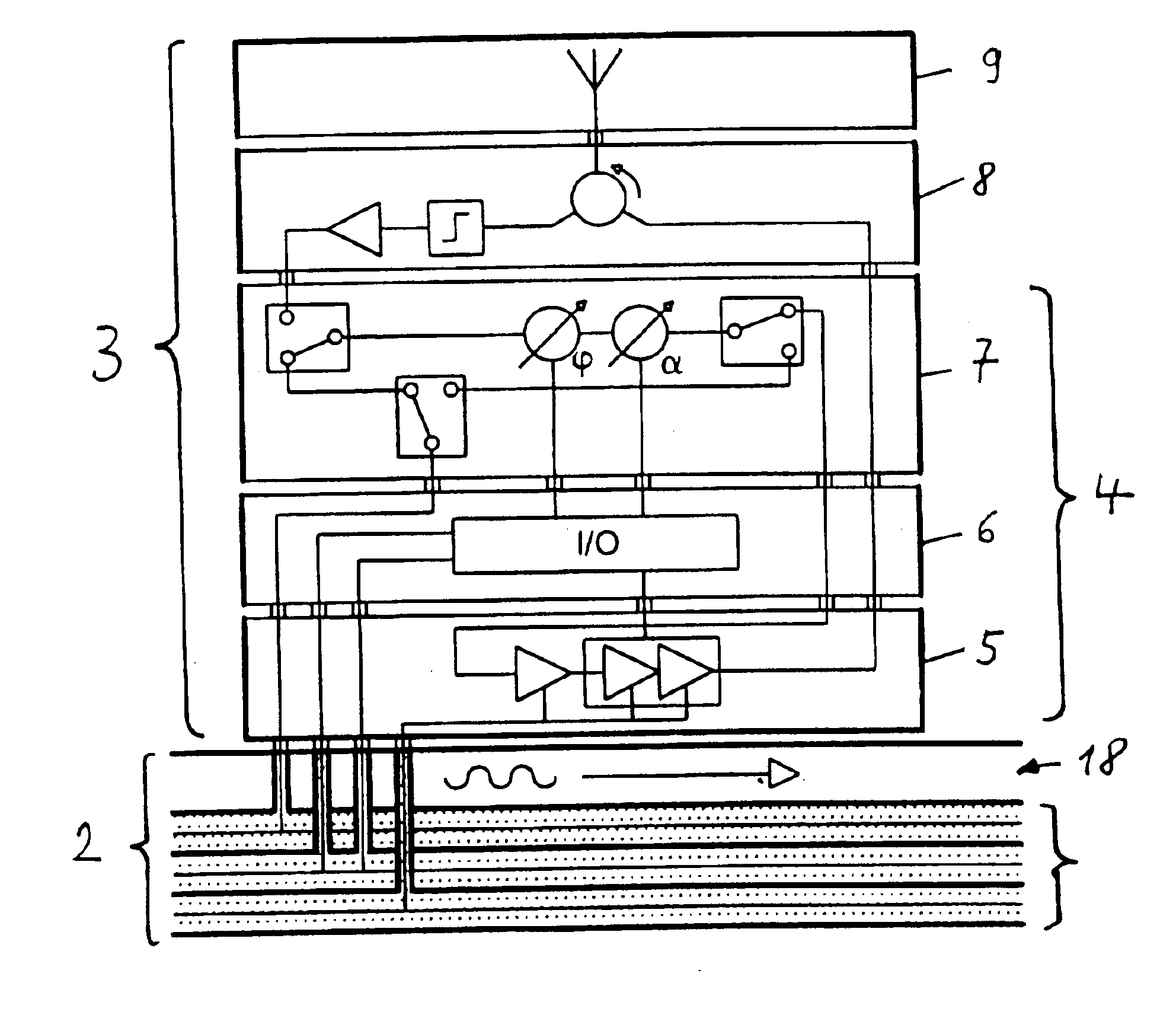
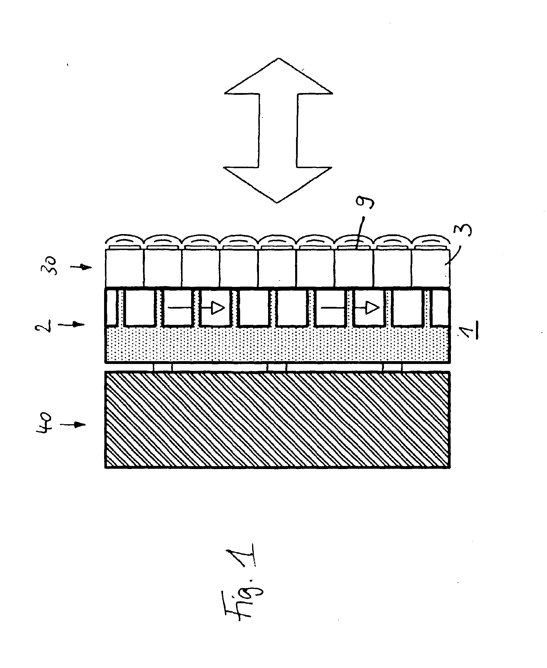
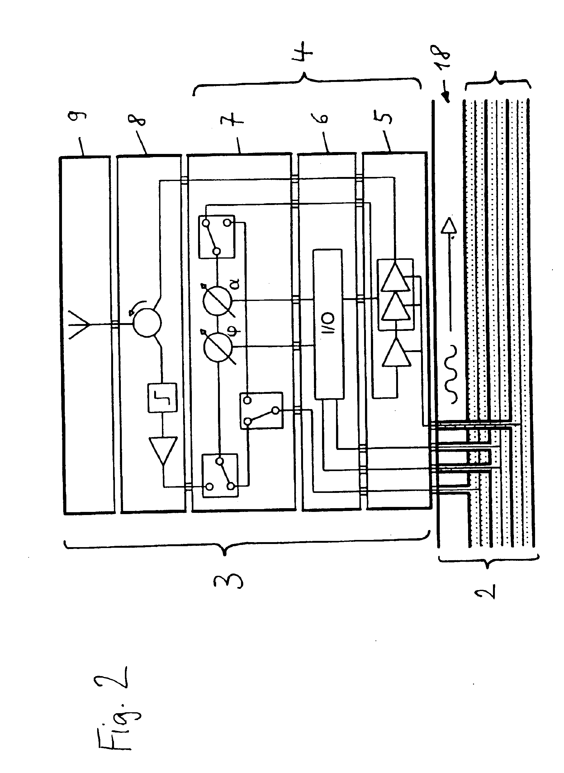
In the radar system shown in FIG. 1 as a schematic simplified side view that overall is designated with reference No. 1, antenna array 30 consists of a larger number of antenna elements 9. The antenna elements 9 are each a component of the transmit / receive module 3. The transmit / receive modules 3 are provided for an radiation and the receipt of a radar signal in the directions of the arrow. A data and supply network 2 is provided for supplying the transmit / receive module 3 with high frequency and data signals and for a power supply and cooling. A system circuit 40 is arranged on the reverse side of data and supply network 2 containing additional processing circuits of the radar system. The system circuit 40 can be installed separately from the data and supply network.

In particular when using the invention in an application system, e.g. in a radar system for airplane wings, only the transmit / receive module and the supply network is built into the wing, whereby the evaluating system c...


PUM


Abstract

A radar system with a phase controlled antenna array that contains a number of data and supply networks (2), which are installed so that they are interchangeable, and a transmit / receive module (3) containing a transmitter and receiver circuit (4) as well as a number of circulator circuits (8) and a number of antenna elements (9) that are coupled via a circulator circuit (8) to the transmitter and receiver circuit (4). Transmitter and receiver circuits (4), circulator circuits (8), and antenna elements (9) are combined in each transmit / receive module (3) and the transmit / receive modules (3) are arranged interchangeably on the radiation side of the radar or EW system (1).

Description

BACKGROUND AND SUMMARY OF THE INVENTIONThis application claims the priority of Application No. 102 005613, filed Jan. 19, 2002, in Germany, the disclosure of which is expressly incorporated by reference herein.The invention concerns a phase controlled antenna subsystem with a passive antenna array which is especially applicable to a radar system, an SAR, for antennas in systems for electronic warfare or deployment guidance, as well as for navigation and communication systems. Possible platforms for the integration of the functions according to the invention are ground, naval systems, airplanes, satellites, drones and guided missiles, as well as buildings or vehicle bound-systems.A radar system with phase controlled antenna array is known from U.S. Pat. No. 5,940,031 which contains a data and supply network and a number of installed and interchangeable transmit / receive modules containing a transmitter and receiver circuit and a number of antenna elements coupled via circulator circui...

Claims


Application Information

Patent Timeline
Patent Type & Authority Patents(United States)
IPC IPC(8): H01Q23/00H01Q21/00G01S7/03G01S7/02H04B1/44
CPCH01Q21/0025H01Q23/00H01Q21/0087
Inventor FELDLE, HEINZ-PETERLEIER, HELMUTMENZEL, WOLFANGSCHREINER, MARC
Owner AIRBUS DEFENCE & SPACE
Why Eureka
Try Eureka