LCD-cell including one spacer exhibiting a dimension and a material property different from another spacers dimension and material property

a liquid crystal display and spacer technology, applied in the field of liquid crystal display cells, can solve the problems of disturbing appearance, undesirable loss of color uniformity, and irregular colors within areas, and achieve the effect of reducing the thickness of the entire spacer, ensuring the mechanical stability of the lcd-cell, and reducing the cost of manufactur

Inactive Publication Date: 2005-04-05
AEG FUR MODERNE
View PDF62 Cites 4 Cited by
  • Summary
  • Abstract
  • Description
  • Claims
  • Application Information

AI Technical Summary

Benefits of technology

By localized structural strengths, the LCD-cell upon cooling can, in a localized manner, also flexibly follow the volume changes of the liquid crystal which obviates the generation of vacuum voids in the liquid crystal. Further, localized increased structural strength assure, on the macroscopic scale, a uniform layer thickness of the cell. A similar effect is achieved by localized heat expansion in which zones with greater heat expansion follow the movement of liquid crystals better and thus, again, the formation of vacuum voids is repressed, while areas having lesser heat expansion are assured a cell of uniform shape. Advantageously, both effects are interrelated, since localized structurally stronger areas show a smaller heat expansion and local yielding areas show greater heat expansion.
At the same time, these second spacers restrain the gravitational settling of the liquid crystals in the cell even under high temperature conditions. This is true, especially in the case of vertical placement or as a result of inertia. As described above, a more pronounced separation of the two plates in the lower cell zone always occasions a corresponding closure of the plates in the upper part. However, the now present second spacers restrain this reflex movement in the upper zone. Because of their dimensioning, in a direction transverse to the two plates, the second spacers are compressed. Thus, the elastic deformation of the second spacers contests the inward movement of the plates with a sufficient counter force to prevent any diminishing of the distance between the two plates. In this way, the cell cannot deform in such a manner that the liquid crystal sinks to the bottom. Consequently, at higher temperatures prevention is assured against a non-uniform coloring from settling, as well as against scratches on the inside surfaces of the plates from vibration.
In this way, the invention exhibits a number of advantages:in higher temperature ranges, there are no irregularities in coloration of the LCD-presentations;in the lower temperature ranges no, or very little, vacuum voids occur;the macroscopic layer thickness of the LCD-cell changes itself very little at low temperatures;scratches by micro-movements of spacers, either by vibration of the cell as a result of vibration tests, mobile applications or the like, are avoided; andvibrations of the transparent plates in the lateral direction are reduced by an amplitude limiting detent.
Since the first spacers assure the mechanical stability of the LCD-cell, there are, as a whole, fewer spacers than are necessary with conventional LCD-cells, an advantage which allows the entire thickness of the spacers to be reduced. This not only reduces the costs of manufacture but also provides the following advantage. With each set of spacers, light is always dispersed or absorbed, and the orientation of the liquid crystal is disturbed. To correct this, the reduction of the entire thickness of the spacer leads to an improvement of the optical quality, in particular to an increase of contrast of the LCD-cell.

Problems solved by technology

This leads to undesirable irregularities of the colors within areas of the display.
Under these conditions, gravity causes the liquid crystals to settle, resulting in an expansion of the lower zone and relative thereto, also a narrowing of the upper zone, which again leads to an undesirable loss of uniformity of color at higher temperatures.
On this account, the plates are unable to sufficiently follow the shrinking of the liquid crystals, whereby, in scattered locations, vacuum voids form in the liquid crystals, which produce a disturbing appearance.
If, on the other hand, the spacers are so yielding that the possibility arises that their elastic contraction is commensurate with the diminishing volume of the liquid crystals, this brings about an undesirable macroscopic alteration of the thickness of the layer, that is, the distance apart of the two facing surfaces of the transparent plate, otherwise known as the “cell gap” of the LCD-cell.
If the spacers are not fastened by adhesion, but by flexible clamping between the two plates, then these spacers, upon vibration of the LCD-cell, approximately in the manner of a conventional vibration test, or in mobile operation, fall into micro-motions, which in turn lead to undesirable scratches on the surface of the transparent plates.
This problem is reinforced by operation at higher temperatures when the spacers, because the expansion of the LCD-cell are less strongly restrained.

Method used


Image

  • LCD-cell including one spacer exhibiting a dimension and a material property different from another spacers dimension and material property
  • LCD-cell including one spacer exhibiting a dimension and a material property different from another spacers dimension and material property
  • LCD-cell including one spacer exhibiting a dimension and a material property different from another spacers dimension and material property

Examples


Embodiment Construction

Detailed reference will now be made to the drawings in which examples embodying the present invention are shown. The drawings and detailed description provide a full and detailed written description of the invention, and of the manner and process of making and using it, so as to enable one skilled in the pertinent art to make and use it, as well as the best mode of carrying out the invention. However, the examples set forth in the drawings and detailed description are provided by way of explanation only and are not meant as limitations of the invention. The present invention thus includes any modifications and variations of the following examples as come within the scope of the appended claims and their equivalents.

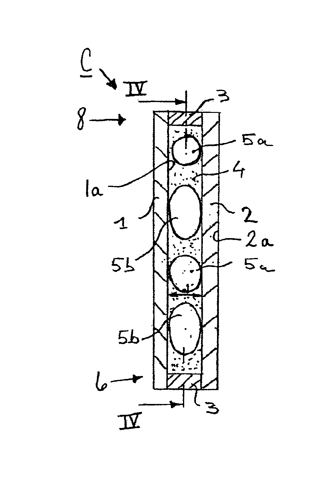
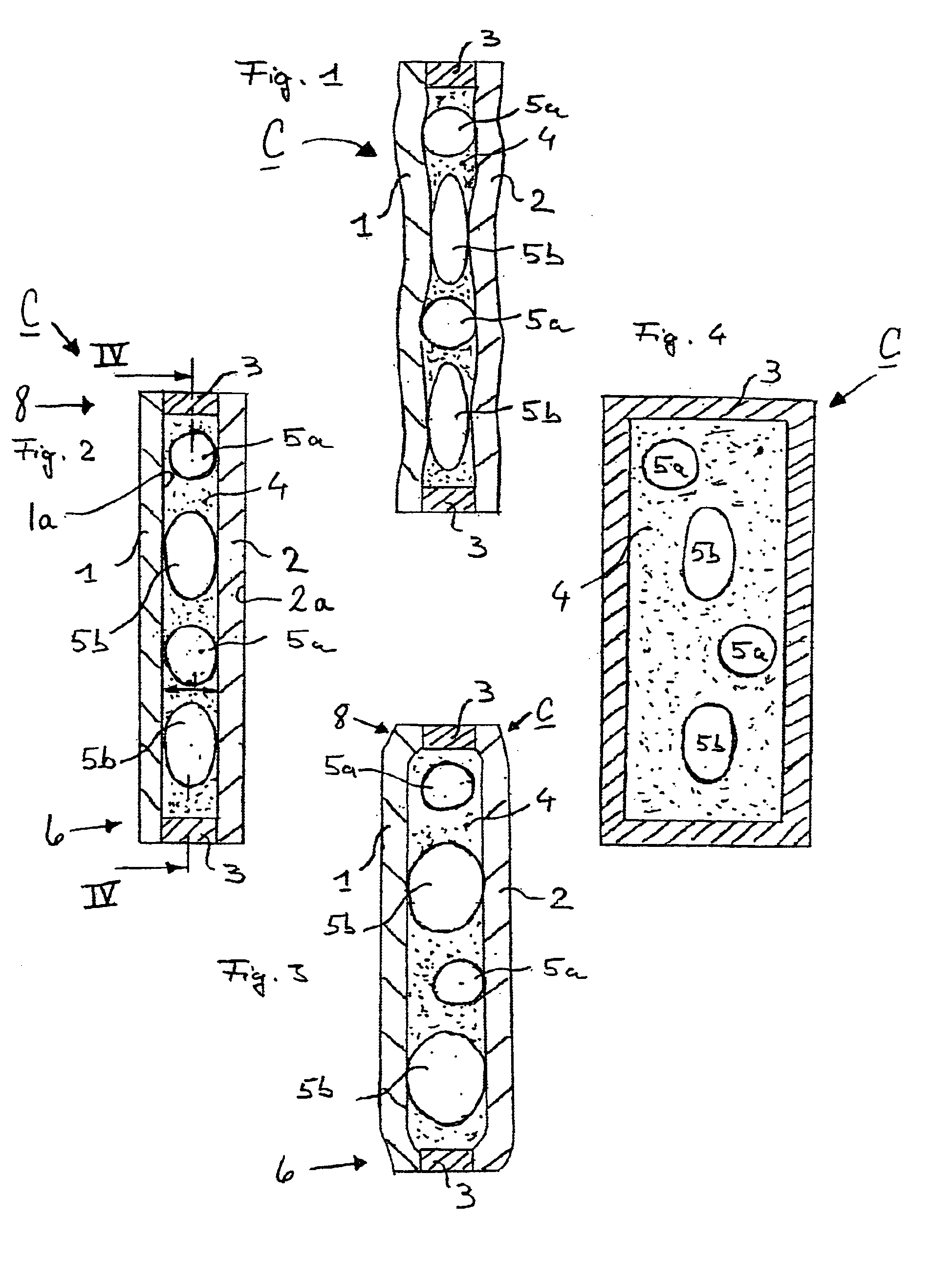
In FIG. 2, an LCD-cell C encompasses two parallel transparent plates, 1 and 2. On the periphery of the plates is placed a seal 3. Within the so constructed cell is placed a liquid crystal material or liquid crystal 4, first spacers 5a and second spacers 5b. In the case of...


PUM

PropertyMeasurementUnit
transparentaaaaaaaaaa
temperatureaaaaaaaaaa
structural strengthaaaaaaaaaa

Abstract

A liquid crystal display (LCD) cell is provided having transparent plates that are substantially parallel to each other and contain a liquid crystal display material. A plurality of spacers are interposed between the transparent plates to define a distance between the plates. At least one of the spacers exhibits dimensions and properties different than another of the spacers. The different dimensions and properties operate to control the distance at various temperatures to prevent non-uniform color effects and vacuum void formations.

Description

FIELD OF THE INVENTIONThe invention concerns a cell in a “Liquid Crystal Display” (hereinafter, “LCD”), the cell being especially adapted to LCD-panels, which operate in a wide temperature range.BACKGROUND OF THE INVENTIONMobile LCD presentations, such as may be found in buses or trains, as well as in stationary LCDs in depots, possess one or more electrically controllable LCD-cells. A single LCD-cell has, in such displays, two, parallel, transparent plates, one behind the other, between which a liquid crystal is captured. Electrodes are arranged on the plates, for example, as a transparent electrode coating, which can be comprised of a plurality of controllable elements. If a voltage is applied between the electrodes, that is, between the individual elements, then certain areas of the LCD-cell with either appear bright or as a “Normally Black Mode LCD”, i.e., dark. Conversely, without applied potential, the areas will appear reversed as to bright and dark.In the case of non-horizon...

Claims


Application Information

Patent Timeline
Patent Type & Authority Patents(United States)
IPC IPC(8): G02F1/13G02F1/1339
CPCG02F1/13392
Inventor BAYRLE, REINERBADER, OTTOBITTER, THOMAS
Owner AEG FUR MODERNE
Why Eureka
Try Eureka