Capacitive type pressure sensor

a technology of capacitive type and pressure sensor, which is applied in the direction of fluid pressure measurement using capacitance variation, instruments, measurement devices, etc., can solve the problems of low cost and design performance that cannot be obtained, and achieve the effect of preventing electromagnetic wave noise and high diaphragm sensitivity

Inactive Publication Date: 2005-04-12
HITACHI LTD +1
View PDF25 Cites 60 Cited by
  • Summary
  • Abstract
  • Description
  • Claims
  • Application Information

AI Technical Summary

Benefits of technology

According to the above-described construction, even if charged particles in the fluid to be measured are about to attach onto the diaphragm surface, the diaphragm surface can be maintain in zero electrical potential by releasing the charge of the charged particles through the electromagnetic shielding electric conductive film and the grounding lead wire formed on the diaphragm surface. Further, the electromagnetic shielding electric conductive film prevents the electromagnetic wave noise which is produced by the charged particles in the fluid to be measured from entering into the sensor, and electrically shields the diaphragm from the external electromagnetic noise.
According to the present invention, since the electromagnetic shielding electric conductive film can cope with attaching of the charged particles in the fluid to be measured, it is sufficient that the insulation film arranged thereunder has a role to electrically insulate the electromagnetic shielding electric conductive film and the diaphragm (which is formed of an electric conductive material such as a semiconductor or the like). Therefore, the insulation film can be thinned as thin as a decimal order μm (for instance, 0.2 μm) because the thickness of the insulation film need not be increased because of the reason described in FIG. 8 (that is, there is no need to take the countermeasure against attachment of the charged particles onto the insulation film). In addition to this, since an acceptable thickness of the electromagnetic shield electric conductive film is also a decimal order μm (for instance, 0.5 μm), the thickness of the diaphragm including the two films can be made still thinner than that of a conventional one. As a result, the high sensitivity of the diaphragm can be maintained.
Furthermore, other object of the present invention is to realize a capacitive pressure sensor which can continuously change the electric capacitance by preventing the movable diaphragm from deforming in a convex state toward the pressure receiving surface side without adding high temperature heat treatment.

Problems solved by technology

However, as problems when a capacitive semiconductor pressure sensor is fabricated on a surface of a semiconductor substrate, there are problems in that the capacitive semiconductor pressure sensor can not be manufactured at a low cost because the method of sealing the diaphragm is complex, and that design performance can not be obtained due to change in the design value of a cavity size or an amount of distortion because the diaphragm displacing depending on a pressure is elastically deformed by its own remaining stress.

Method used


Image

  • Capacitive type pressure sensor
  • Capacitive type pressure sensor
  • Capacitive type pressure sensor

Examples


third embodiment

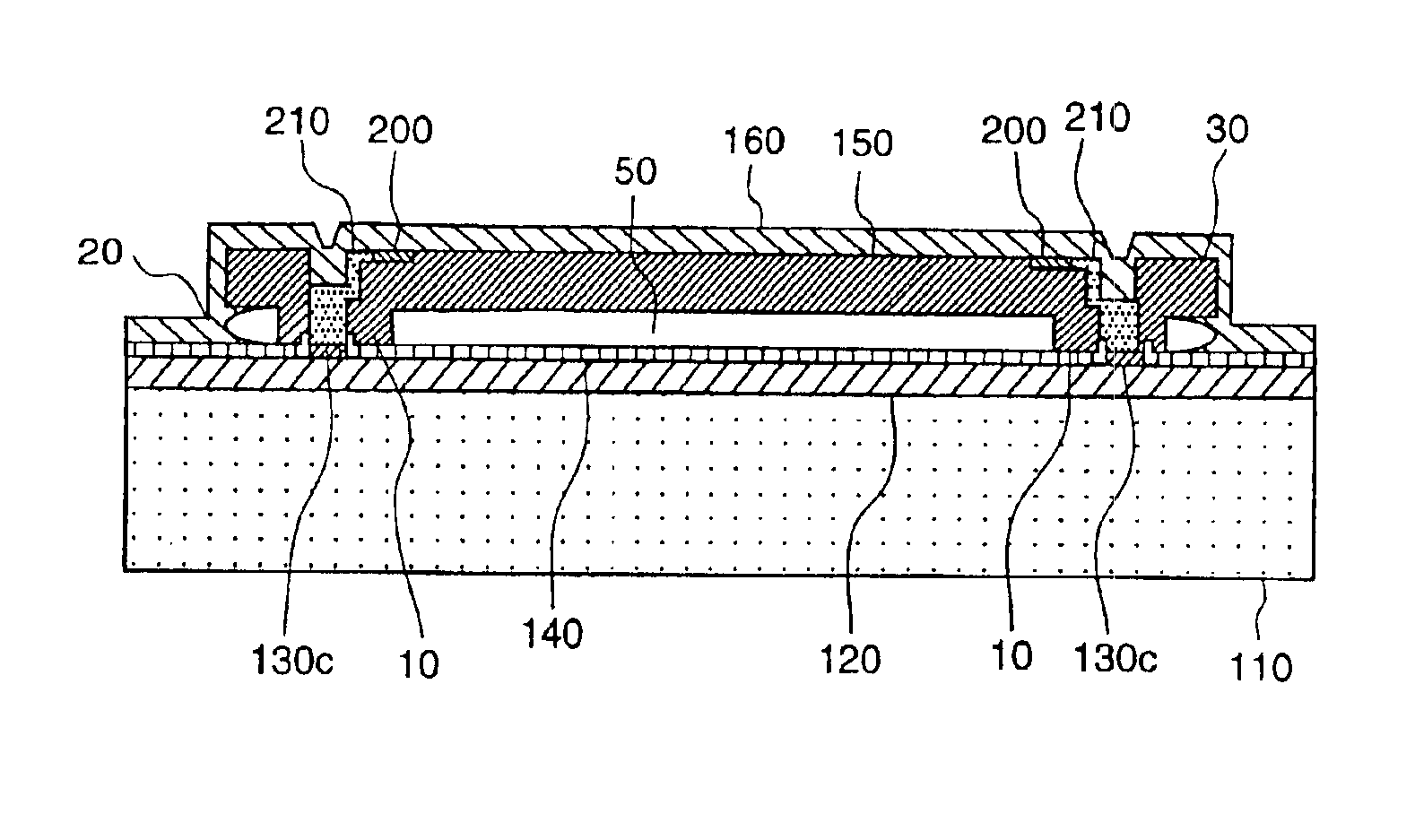
FIG. 7 is a cross-sectional view showing a piezo-resistive pressure sensor to which the present invention is applied.

The pressure sensor is composed of stages 10, a diaphragm sealing part 20, a connection part 30, a cavity 50, semiconductor substrate 110, a dielectric body 120, a diaphragm electric wiring 130c, a barrier layer 140, a diaphragm construction 150, an LPCVD silicon oxide film 160, a piezo-resistive element 200 and an electric conductive body 210.

Pressure of a medium to be measured such as air or the like deforms the diaphragm construction 150 through the LPCVD silicon oxide film 160. The piezo-resistive element 200 arranged at a position on the diaphragm construction 150 where the deformation becomes maximum changes its resistance value corresponding to the deformation. The change in the strain resistance is transmitted to a detecting circuit through the electric conductive body 210, the connection part and the diaphragm wiring 130c. Therefore, Since the cavity 50 of 0....


PUM

PropertyMeasurementUnit
thicknessaaaaaaaaaa
thicknessaaaaaaaaaa
resistivityaaaaaaaaaa

Abstract

By sealing a diaphragm with less processes and lower cost and reducing deformation due to remaining stress, a stable and highly reliable pressure sensor construction is proposed. The pressure sensor is low in measurement error and small in floating capacitance and leakage current and good in characteristic. As a means to attain the above object, a polycrystalline silicon diaphragm is sealed with a silicon oxide film deposited through a LPCVD method and then completely covered. The diaphragm is placed on a surface of a semiconductor substrate with a nearly constant gap of 0.15 to 1.3 μm, and has difference-in-grade constructions of a deformation reducing means due to remaining stress.

Description

BACKGROUND OF THE INVENTIONThe present invention relates to a capacitive type pressure sensor for detecting fluid pressure, and particularly to a construction of a pressure sensor used for controlling an engine of vehicle and a method of manufacturing the sensor utilizing a semiconductor micro-machining technology.As a conventional pressure sensor, pressure sensors are disclosed, for example, in Japanese Patent Publication No.62-502645 and Japanese Patent Laid-open No.6-252420.Japanese Patent Publication No.62-502645 proposes a construction of a pressure sensor and a method of manufacturing the sensor. The pressure sensor is composed of a semiconductor substrate; a solid material having a central portion capable of being deformed, the central portion being arranged on the substrate though a cavity, a peripheral portion bonded to the substrate and an etch channel portion extending to the central portion through the peripheral portion; and a material for sealing the etch channel.Japan...

Claims


Application Information

Patent Timeline
Patent Type & Authority Patents(United States)
IPC IPC(8): G01L9/00G01L9/12
CPCG01L9/0073
Inventor HORIE, JUNICHIONOSE, YASUOICHIKAWA, NORIOKURYU, SEIJISHIMADA, SATOSHISAITO, AKIHIKOHANZAWA, KEIJIMATSUMOTO, MASAHIROMORIYA, HIROSHIYASUKAWA, AKIOMIYAZAKI, ATSUSHI
Owner HITACHI LTD
Why Eureka
Try Eureka