
Electrochemical process for effecting redox-enhanced oil recovery

a redox-enhanced, oil-recovery technology, applied in the field of oil production, can solve the problems of the storage energy in the reservoir is often dissipated, and the recovery methods that utilize electrodes often encounter problems affecting the quantity and quality of recovered oil, so as to stimulate oxidation and reduction reactions, reduce the viscosity of oil compounds, and increase the effect of oil mobility

Inactive Publication Date: 2005-04-12
ELECTRO PETROLEUM
View PDF11 Cites 34 Cited by
  • Summary
  • Abstract
  • Description
  • Claims
  • Application Information

AI Technical Summary

Benefits of technology

The first and second electrodes are installed in an electrically conductive formation, such as a formation having a moisture content sufficient to conduct electricity. A DC biased current with a ripple component is applied through the electrodes under conditions appropriate to create an electrical field through the oil formation. The current is regulated to stimulate oxidation and reduction reactions in the oil. As redox reactions occur, long-chain compounds such as heavy petroleum hydrocarbons are reduced to smaller-chain compounds. The decomposition of long-chain compounds decreases the viscosity of the oil compounds and increases oil mobility through the formation such that the oil may be withdrawn at the recovery well. Electrochemical reactions in the formation also upgrade the quality and value of the oil that is ultimately recovered. The system can be used with a multiplicity of cathodes and anodes placed in vertical, horizontal or angular orientations and configurations.

Problems solved by technology

The stored energy in the reservoir dissipates as oil production progresses and eventually becomes insufficient to force the oil to the producing well.
Oil recovery is frequently limited by capillary forces that impede the flow of viscous oil through interstitial spaces in the oil-bearing formation.
Oil recovery methods that utilize electrodes frequently encounter problems affecting the quantity and quality of the recovered oil.
In addition, systems using DC current consume relatively large amounts of electricity with corresponding large energy costs.

Method used


Image

  • Electrochemical process for effecting redox-enhanced oil recovery
  • Electrochemical process for effecting redox-enhanced oil recovery
  • Electrochemical process for effecting redox-enhanced oil recovery

Examples


Embodiment Construction

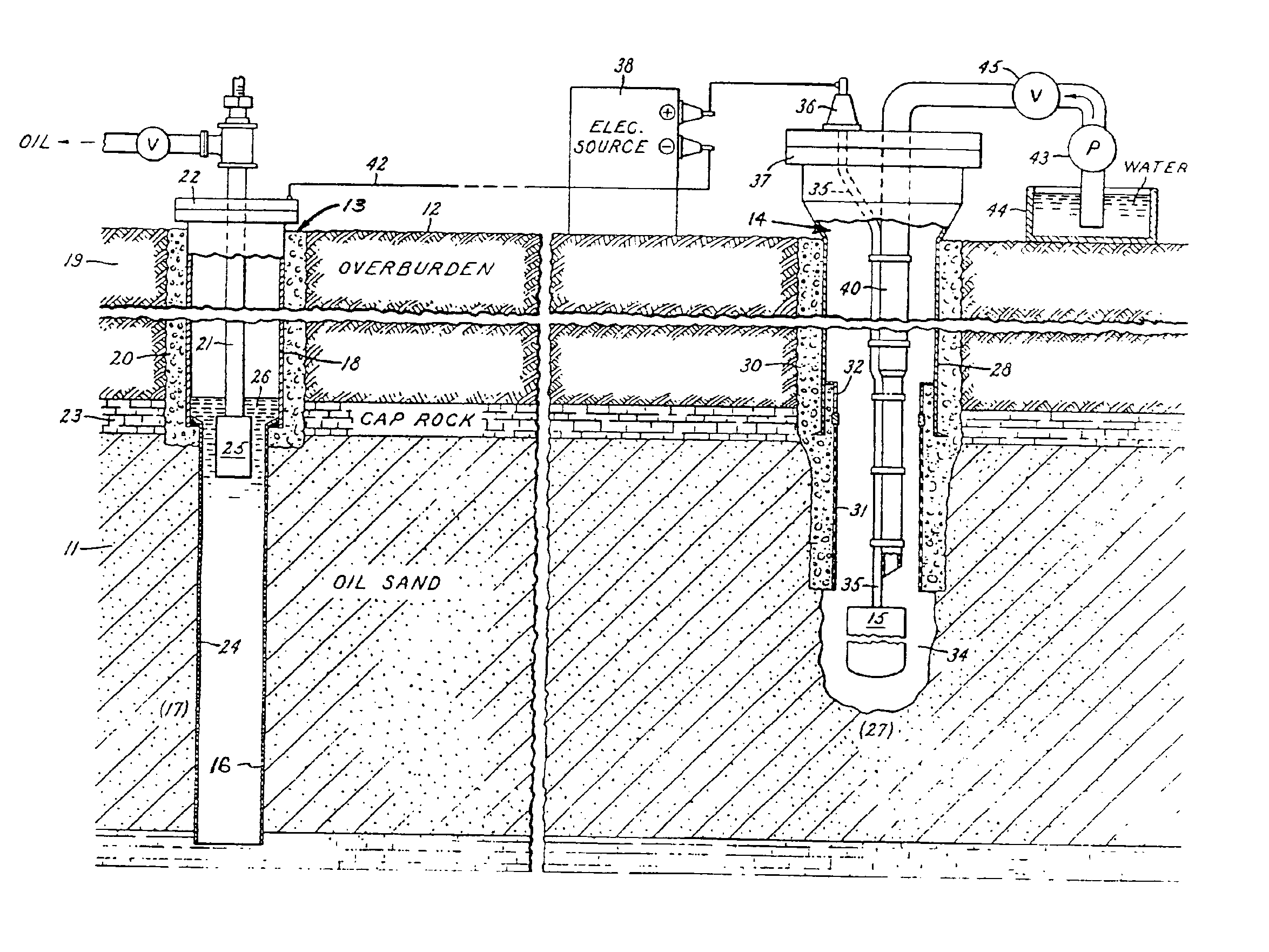
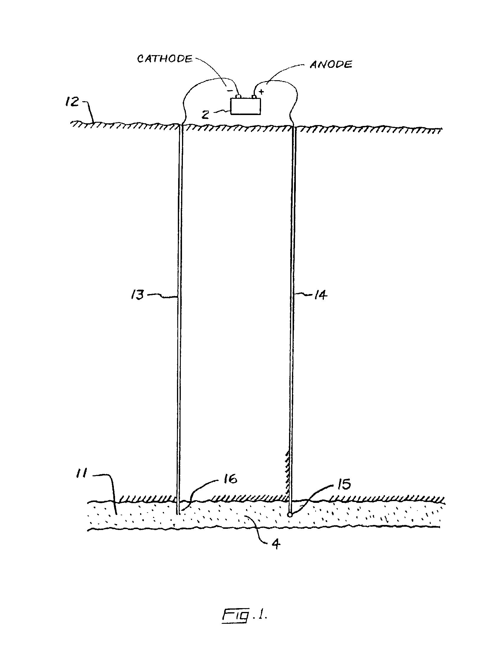
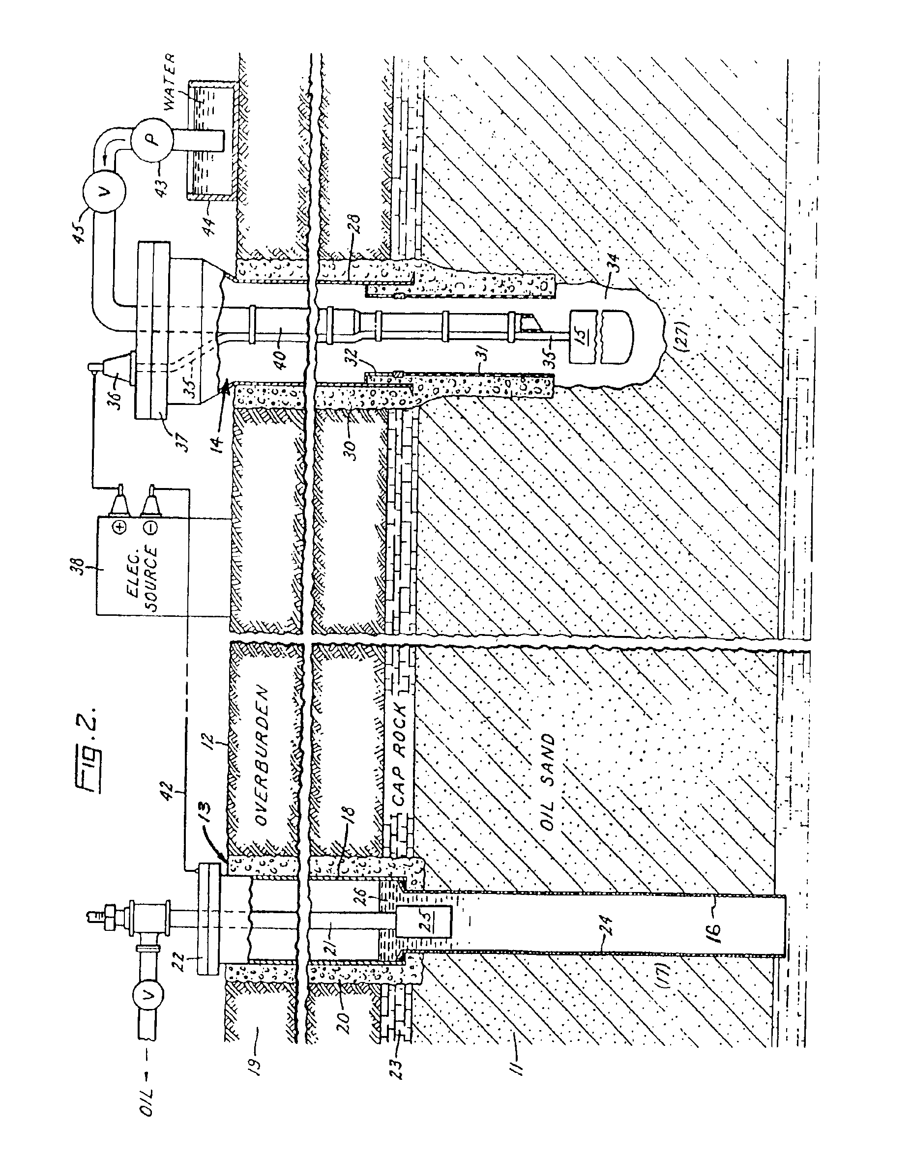
Referring to the Figures in general, and to FIG. 1, specifically, the reference number 11 represents a subterranean formation containing crude oil. The subterranean formation 11 is an electrically conductive formation, preferably having a moisture content above 5 percent by weight. As shown in FIG. 1, formation 11 is comprised of a porous and substantially homogeneous media, such as sandstone or limestone. Typically, such oil-bearing formations are found beneath the upper strata of earth, referred to generally as overburden, at a depth of the order of 1,000 feet or more below the surface. Communication from the surface 12 to the formation 11 is established through spaced-apart boreholes 13 and 14. The hole 13 functions as an oil-producing well, whereas the adjacent hole 14 is a special access hole designed for the transmission of electricity to the formation 11.

The present invention can be practiced using a multiplicity of cathodes and anodes placed in vertical, horizontal or angula...


PUM


Abstract

A method is provided for recovering oil from a subterranean oil-bearing formation. One or more pairs of electrodes are inserted into the ground in proximity to a body of oil in said formation. A voltage difference is then established between the electrodes to create an electric field in the oil-bearing formation. As voltage is applied, the current is manipulated to induce oxidation and reduction reactions in components of the oil. The oxidation and reduction reactions lower the viscosity in the oil and thereby reduce capillary resistance to oil flow so that the oil can be removed at an extraction well.

Description

FIELD OF THE INVENTIONThe present invention relates generally to oil production, and more particularly to an improved method for recovering oil from subterranean oil reservoirs with the aid of electric current.BACKGROUND OF THE INVENTIONWhen crude oil is initially recovered from an oil-bearing earth formation, the oil is forced from the formation into a producing well under the influence of gas pressure and other pressures present in the formation. The stored energy in the reservoir dissipates as oil production progresses and eventually becomes insufficient to force the oil to the producing well. It is well known in the petroleum industry that a relatively small fraction of the oil in subterranean oil reservoirs is recovered during this primary stage of production. Some reservoirs, such as those containing highly viscous crude, retain 90 percent or more of the oil originally in place after primary production is completed. Oil recovery is frequently limited by capillary forces that i...

Claims


Application Information

Patent Timeline
IPC IPC(8): E21B43/24E21B43/16E21B43/22
CPCE21B43/16E21B43/2401E21B2043/0115E21B41/0099
Inventor WITTLE, J. KENNETHBELL, CHRISTY W.
Owner ELECTRO PETROLEUM
Learn More