Elastomeric spring assembly for a railcar and method of making same

a technology of elastomeric springs and rail cars, which is applied in the direction of mechanical equipment, machine supports, transportation and packaging, etc., can solve the problems of large energy and excessive resultant, the spring assembly must have great strength or it will easily fail under substantial loads, and the spring assembly utilizing a steel on steel friction interface, which is not suitable for some applications, and achieves the effect of enhancing the performance characteristics of the spring assembly

Inactive Publication Date: 2005-04-12
MINER ENTERPRISES INC
View PDF24 Cites 40 Cited by
  • Summary
  • Abstract
  • Description
  • Claims
  • Application Information

AI Technical Summary

Benefits of technology

In view of the above, and in accordance with one aspect, there is provided an elastomeric spring assembly for a railcar. In one form, the elastomeric spring assembly includes an elongated body of elastomeric material having a series of axially spaced members coaxially arranged and wholly embedded within the body of elastomeric material. The majority of the embedded members are configured to resist radial outward movement of said elastomeric material while causing the elastomeric material to react in an axial direction between confronting surfaces defined by the members upon axial deflection of the elastomeric spring whereby enhancing performance characteristics of the spring assembly.
According to a second aspect, there is provided a railcar apparatus for absorbing, dissipating and returning energy imparted thereto. The railcar apparatus includes a housing and an elastomeric spring assembly adapted to be mounted within a cavity or chamber defined by the housing. The elastomeric spring assembly has an elastomeric body defining an elongated axis along with an inner closed marginal edge and an outer marginal edge. The elastomeric body has axially spaced first and second ends and a series of axially spaced members arranged generally coaxial relative to said elongated elastomeric body. In a preferred form, the majority of such members are wholly embedded within and between the inner closed marginal edge and the outer marginal edge of the elastomeric body. Moreover, such members are configured to resist radial outward movement of the elastomeric body while causing elastomer between confronting surfaces of the members to react in an axial direction upon axial deflection of the spring assembly whereby significantly increasing the spring assembly performance including energy absorption capabilities without increasing the size of the outer marginal edge of the elastomeric body.
According to another aspect, an elastomeric spring assembly is provided for a railroad car apparatus. The elastomeric spring assembly includes an elongated tubular member formed from an elastomer and a coil spring arranged generally coaxial relative to and extending substantially the length of the tubular member. In this form, the tubular member has an inner closed marginal edge and an outer marginal edge along with axially spaced first and second ends. The coil spring includes helical convolutions wholly embedded in the elastomer between the inner closed marginal edge and the outer marginal edge of the tubular member. An inner radial surface of the majority of the helical convolutions restricts radial outward movements of the elastomer encompassed thereby while confronting axially spaced surfaces on the helical convolutions allow the elastomer to react in an axial direction whereby enhancing the spring assembly performance including energy absorption capabilities without increasing the cross-sectional size of the tubular member.
According to this aspect, the tubular member is formed from an elastomer selected from a class of elastomers wherein the plastic to elastic strain ratio is greater than 1.5 to 1. Additionally, and according to this aspect, the axial distance between opposed ends of the coil spring is substantially equivalent to the axial length of the elastomeric member. Preferably, opposed and radially inner margins of the tubular member are recessed to reduce the radial outwardly directed forces applied to opposed spring ends during axial deflection of the spring assembly.
Accordingly, it is an object of this invention to provide a railcar spring assembly which is both strong and reliable while remaining economical to manufacture.
Another object of this invention is to provide a railcar spring assembly which embodies the advantages inherent with elastomers, while offering performance characteristics which exceed known elastomeric springs.

Problems solved by technology

Significantly large amounts of energy and excessive resultant dynamic impacts are developed between multiple railcars during the make-up and operation of a 100 railcar or train consist.
Accordingly, the materials forming the spring assemblies must have great strength or they will readily fail under the substantial loads, and energy impacts repeatedly imparted thereto during daily operation of the railcars and under adverse temperature conditions.
The spring loaded steel springs, utilizing a steel on steel friction interface, however, proved ineffective in some applications because of seizing and galling problems.
Those spring assemblies having a column of rubber-like material with a coil spring wound thereabout have also proven unsatisfactory since the rubber-like material, when compressed under extremely heavy loads, tends to plasticize and squeeze out between the spring coils, thus, creating other serious drawbacks and related problems.
Moreover, such spring assemblies have not yielded satisfactory spring rates.
Of course, increasing the capacity of railcars tends to add to the dynamic loads placed upon the draft gears and other railcar suspension components.
The size constraints of the housing wherein the spring assemblies are mounted, however, limit both the number and size of elastomeric pads which can be stacked therewithin.
Since such springs are limited in size they are frequently subjected to increased wear due to increases in load carrying capacities of the railcars and result in a greater need for maintenance along with higher replacement needs whereby adding to the overall cost of rail transportation.

Method used


Image

  • Elastomeric spring assembly for a railcar and method of making same
  • Elastomeric spring assembly for a railcar and method of making same
  • Elastomeric spring assembly for a railcar and method of making same

Examples


Embodiment Construction

While the present invention is susceptible of embodiment in multiple forms, there is shown in the drawings and will hereinafter be described a preferred embodiment of the invention, with the understanding this disclosure is intended to set forth an exemplification of the invention which is not intended to limit the invention to the specific embodiment illustrated and described.

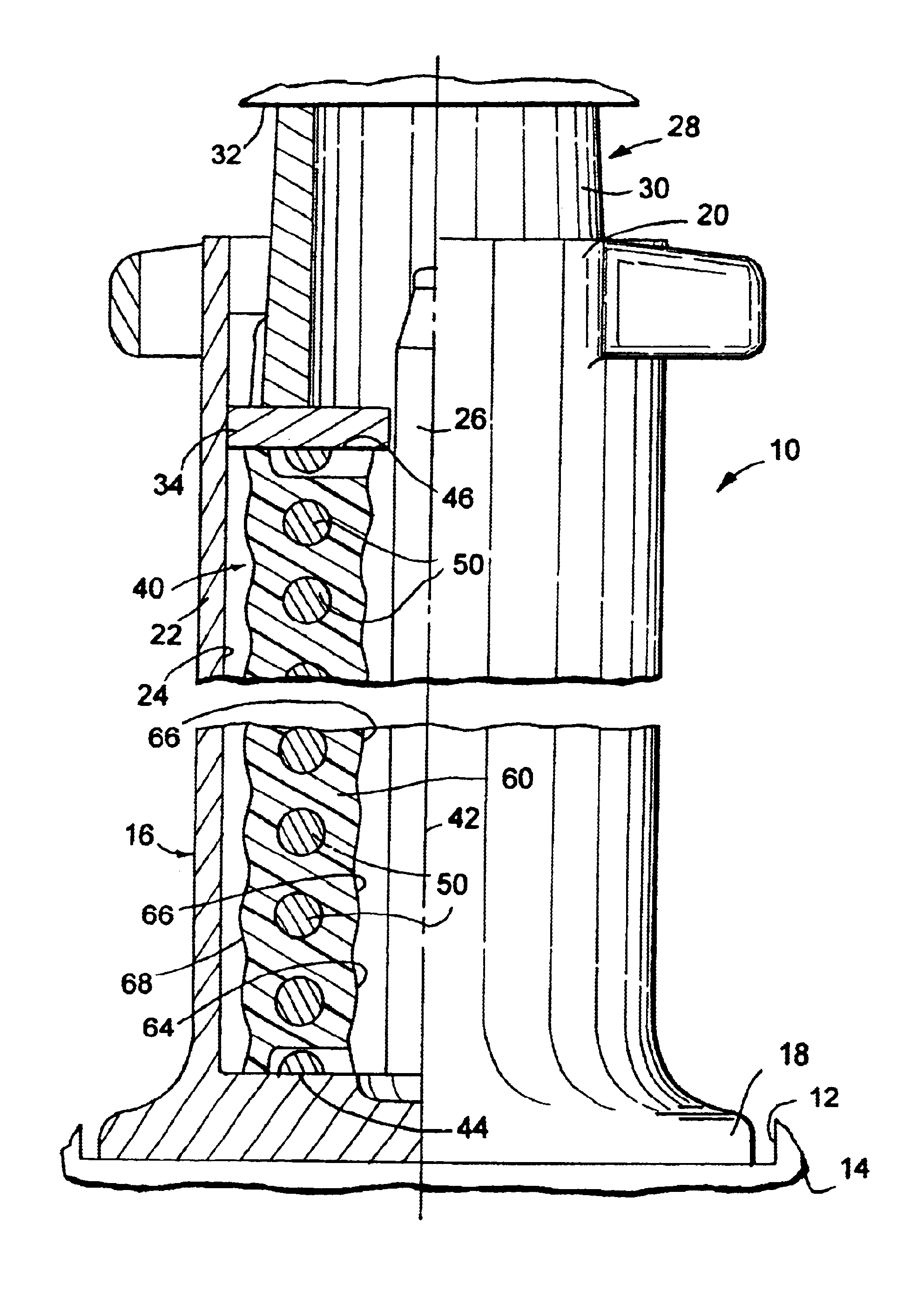
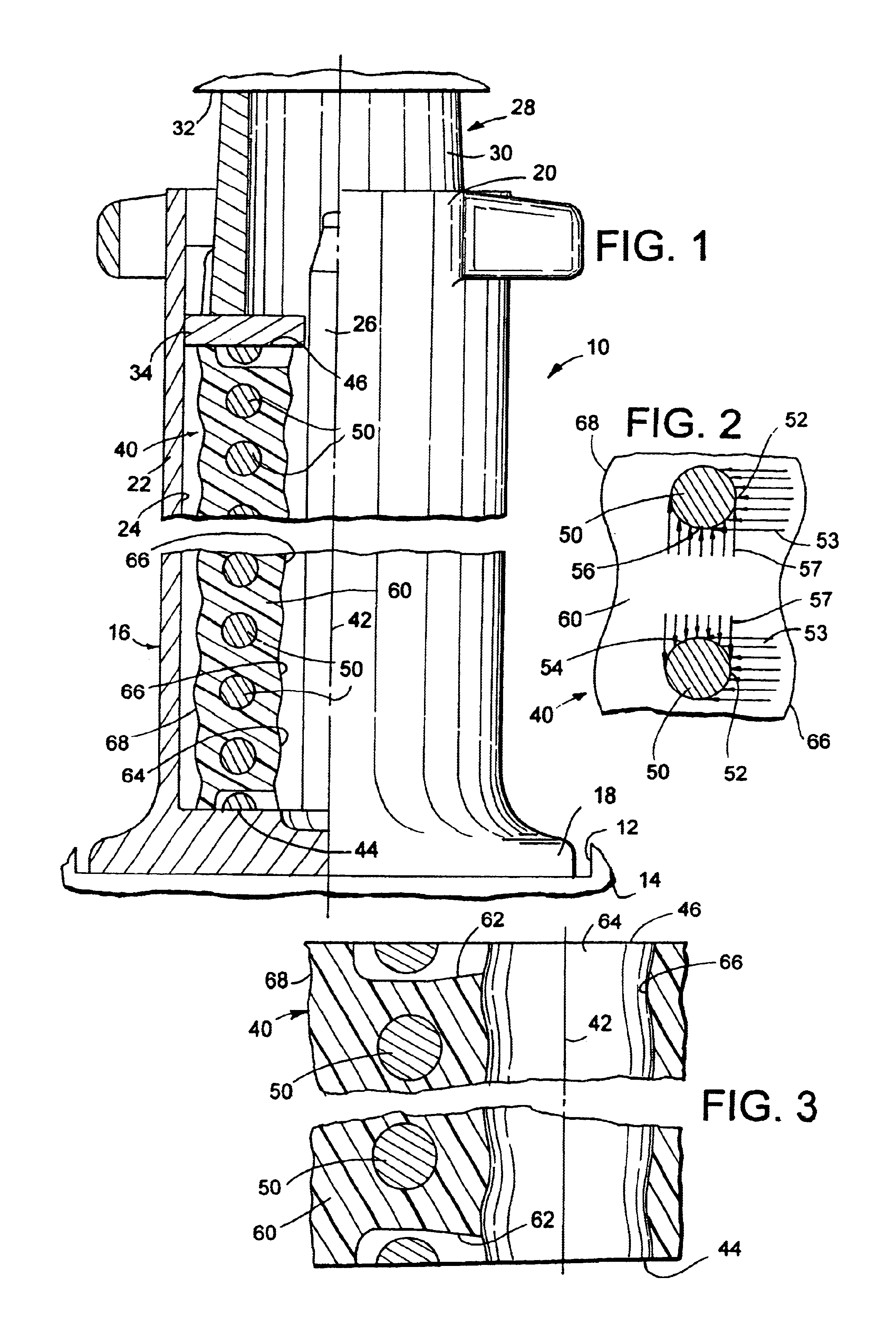
Referring now to the drawings, wherein like reference numerals indicate like parts throughout the several views, there is shown in FIG. 1 a railcar apparatus generally identified by reference numeral 10. As will be appreciated, the railcar apparatus 10 can take a myriad of designs and shapes without detracting or departing from the spirit and scope of the present invention. In the exemplary embodiment, apparatus 10 is shown as a railcar draft gear assembly typically accommodated within a pocket 12 on a conventional railcar, generally identified by numeral 14. It should be appreciated, the teachings and advanta...


PUM


Abstract

An elastomeric spring assembly for a railcar apparatus is disclosed. The elastomeric spring assembly includes an elongated body of elastomeric material having a series of axially spaced members coaxially arranged and wholly embedded within the body of elastomeric material. The majority of the embedded members are configured to resist radial outward movement of said elastomeric material while causing the elastomeric material to react in an axial direction between confronting surfaces defined by the members upon axial deflection of the elastomeric spring whereby enhancing performance characteristics of the spring assembly. A method of making an elastomeric spring assembly is also disclosed.

Description

FIELD OF THE INVENTIONThe present invention generally relates to an elastomeric spring assembly for a railcar and, more particularly, to a spring assembly including an elongated body of elastomer material having a series of axially spaced members wholly embedded and coaxially arranged therewithin, with each member being configured to resist radial outward movement of the elastomer while causing the elastomer to react between axially confronting surfaces of the members upon axial deflection of the spring assembly whereby enhancing spring assembly performance.BACKGROUND OF THE INVENTIONAn energy absorption apparatus or spring is known to be used on a railcar in various applications and between two masses. For example, a spring is commonly used and forms an integral part of a railroad car side bearing. A railroad car side bearing is typically disposed to opposite lateral sides of a car body between a centerpiece or bolster of a wheeled truck and an underside of a railroad car body. Dur...

Claims


Application Information

Patent Timeline
Patent Type & Authority Patents(United States)
IPC IPC(8): B61F5/02B61F5/14F16F3/12F16F3/00
CPCF16F3/12B61F5/142
Inventor SALIS, KEITH A.
Owner MINER ENTERPRISES INC
Why Eureka
Try Eureka